6
EN
E L VO X
CN2
CN1
CN1
M
+A
CH
+D
-
+
V2
V3
M
V1
AU
6E
A
C
2
2
6E
6P
6S
6
5
3
3
AU
1
7
E
1
6
CH
1
3
2
4
5
3
5
6
CH
CH CH S
V
2 1
8
1 1
10
8
7
9
12
13
V
M
3
1
2
6
5
4
7
13
12
10
1 1
9
V2
V3
V1
M
S
CH 6 5 3
1
2
V
8
C
D
CT
M
+T
V
B
A
L1
4
6
7
3
V2
PRI
M1 V1
M2
AU
3
B
C2 1
A
2
- + S
8
6 7
+T
- AM
C1
15 0 S1
F
F
F
C2
C2
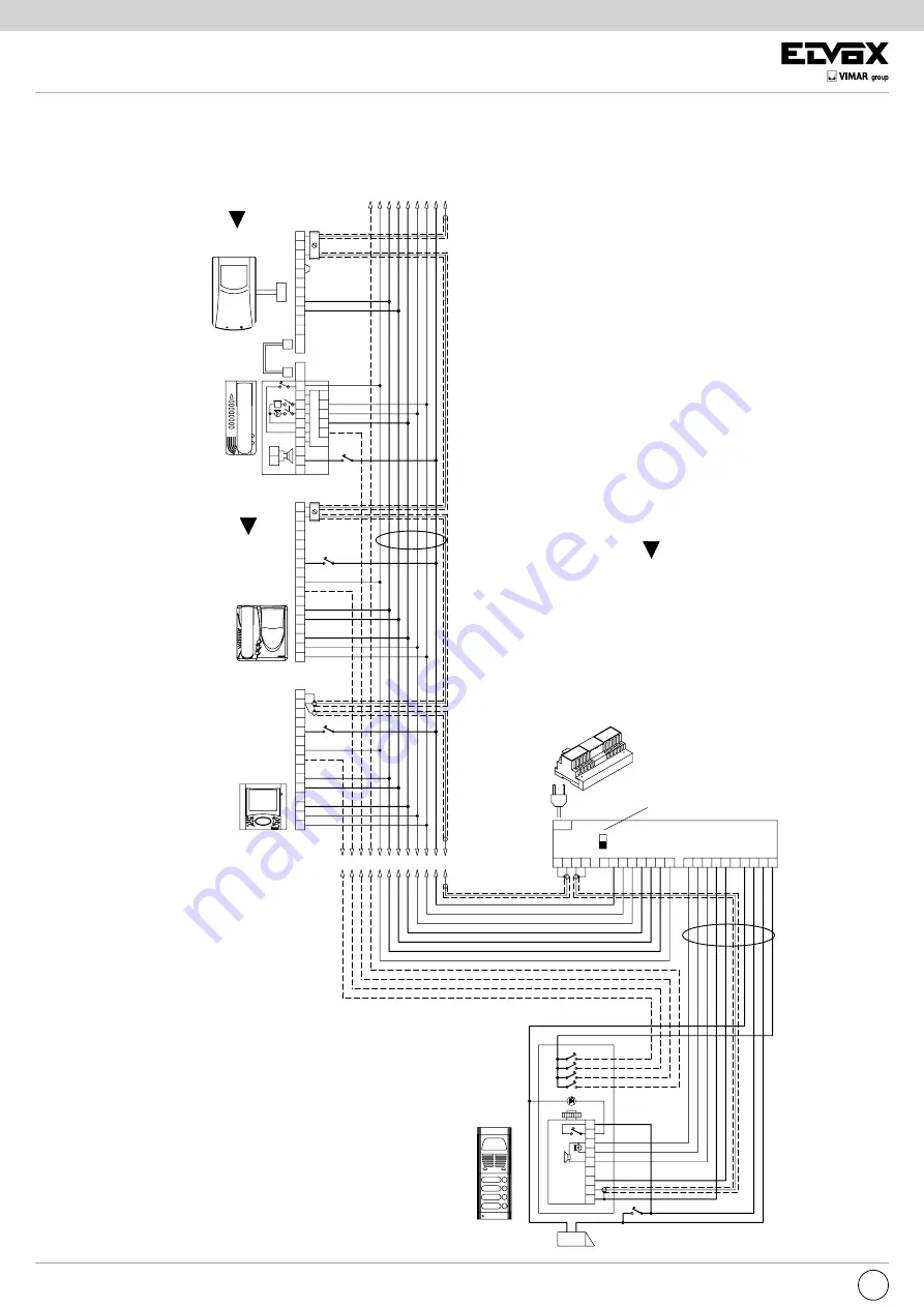
“SOUND SYSTEM” SINGLE AND MULTIPLE RESIDENCE VIDEO DOOR ENTRY SYSTEM WITH POWER SUPPLY TYPE
6680/C17 AND CONVERSATION PRIVACY
POWER SUPPLY
type 6680/C17
B/W MONITOR
type 6300
type 6320
type 6500
DIAGRAM N° vc4476R2
*
COLOUR MONITOR
type 6303
B/W MONITOR
type 6000 +
type 6200 +
type 6145 +
type 6155
COLOUR MONITOR
type 6003 +
type 6200 +
type 6145 +
type 6155
CABLE
type 61/001
type 61/003
CABLE
type 61/001
type 61/003
N.B.
In the event of buzzing on
the audio line, move the
switching module “A-B”
located under the cover to
position “A”.
Mains
A- Video entrance panel 3300, 8000, 8100, 1200
PATAVIUM and letter box 2550/301-302 series
B- Additional door lock button
C- 12V~ electric lock
D- Camera with speech unit
type 559, 559A, 559B, 559G, 558, 570,
570G, 571, 559C and 570C+930A
Note:
For the connection of camera type 559A
and 559B see variation 17
E- Card for conversation privacy type 6155
L1- Led module for entrance panel
(10 module LED max.)
30 module LED con Art. M832
40 module LED con Art. 832/030
MONITOR CABLE RISER
Connect 75 Ohm resistor (sup-
plied) to the last monitor, between
terminals V2-M.
*
N.B.
The monitors have a microswitch
on the back, set it to “witht conver-
sation privacy”.
N.B.
The monitors have a microswitch
on the back (or underneath) for
connection “with coaxial/without
coaxial”; set the microswitch to
“coaxial”.
* *
* * *
T h e “ C O N V E R S A T I O N
PRIVACY” function is normally
deactivated. To activate or deacti-
vate the function see conversation
privacy programming.
COLOUR MONITOR
type 6600
type 660A
type 6700
* *
* * *


