7/32
GB
Art. 68TC/K, 68TU/K
INSTALLATION
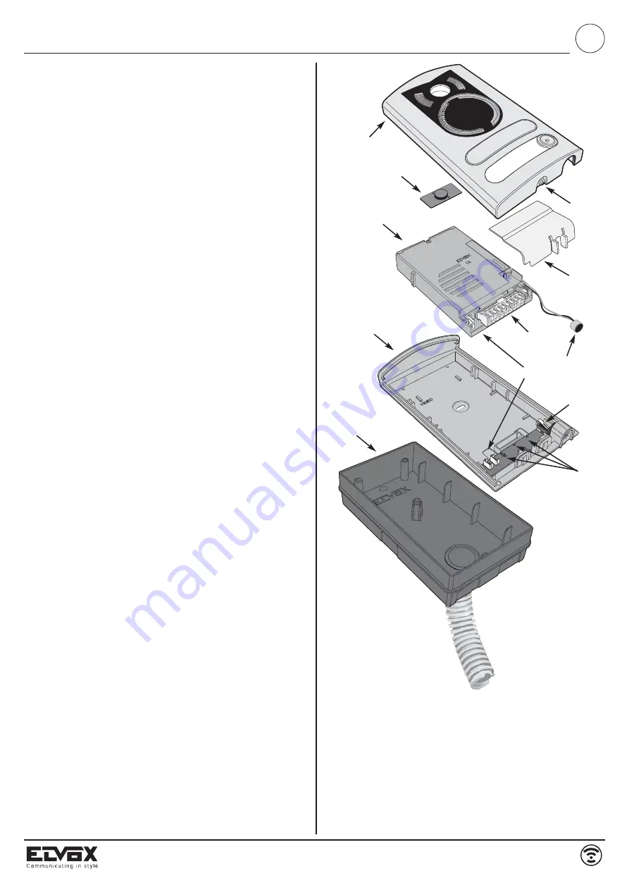
Installation of entrance panel (type 13K1), flush-mounting version
-
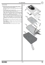
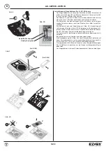
Install the flush-mounting back box (D) on the wall with the bottom edge
at a height of approx. 1.65m from the ground
-
Open the entrance panel by loosening the screw underneath the plate
(G) and remove the light diffuser (H).
-
Fit the frame (C) to the flush-mounting back box (D)
-
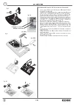
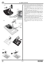
Reposition the camera in the frame and the microphone in the special
housing, refitting the plug as shown in Fig. 3.
-
Connect the camera to the name card lighting LED board using the two
cable harnesses (harness with red/black wire for LED power supply and
harness with two green wires for connection of a second call button, if re-
quired) Fig. 3B.
-
Make the connections to the installation on the removable terminal block
(L).
In the case of installation for two-family video door entry systems:
-
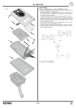
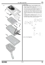
Remove the blanking module (E) Fig. 4, from the back of the plate using
a screwdriver, working in sequence from bottom to top (first remove the
end section, then key 1 and finally the blanking module).
-
Fit the external key (F) (supplied) to the plate by pushing it lightly into
place.
-
Insert the light diffuser (H) to ensure even lighting of the name cards.
-
Remove the lens ring (R) and fit the lens cover (S) (see Fig. 4B).
- Close the entrance panel, securing it to the frame with the aid of a screw-
driver.
B
C
D
I
N
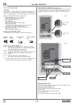
Fig. 2B
A
H
G
O
L
M
S
Summary of Contents for 68TC/K
Page 29: ...29 32 Art 68TU K93 NOTE ...


