background image

OPERATION

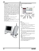
Video switchboard type 735B can operate in two modes: inter-

nal or external, to select the mode use the d. key on the video
switchboard, the d. key will remain lit in external mode, whe-
reas the LED will switch off in internal mode. 

1) External 

operation: 

each call from the main entrance panel

will be sent directly to the interphone / monitor cable riser
without being intercepted by the switchboard. 
However this condition still allows the receipt of porter calls,
calls direct to the switchboard and signalling of conversa-
tion in progress between external entrance panel and inter-
nal interphone / monitor. 

Call direct to video switchboard from main entrance
panel:

if the video switchboard is operating in external

mode, it is possible to receive calls from the main entrance
panel using the direct call number, see “Device number” pa-
rameter 

Porter calls:

if the video switchboard is operating in exter-

nal mode, calls to the concierge are still recorded and di-
splayed on the LCD screen in the log section. 

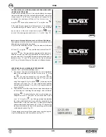
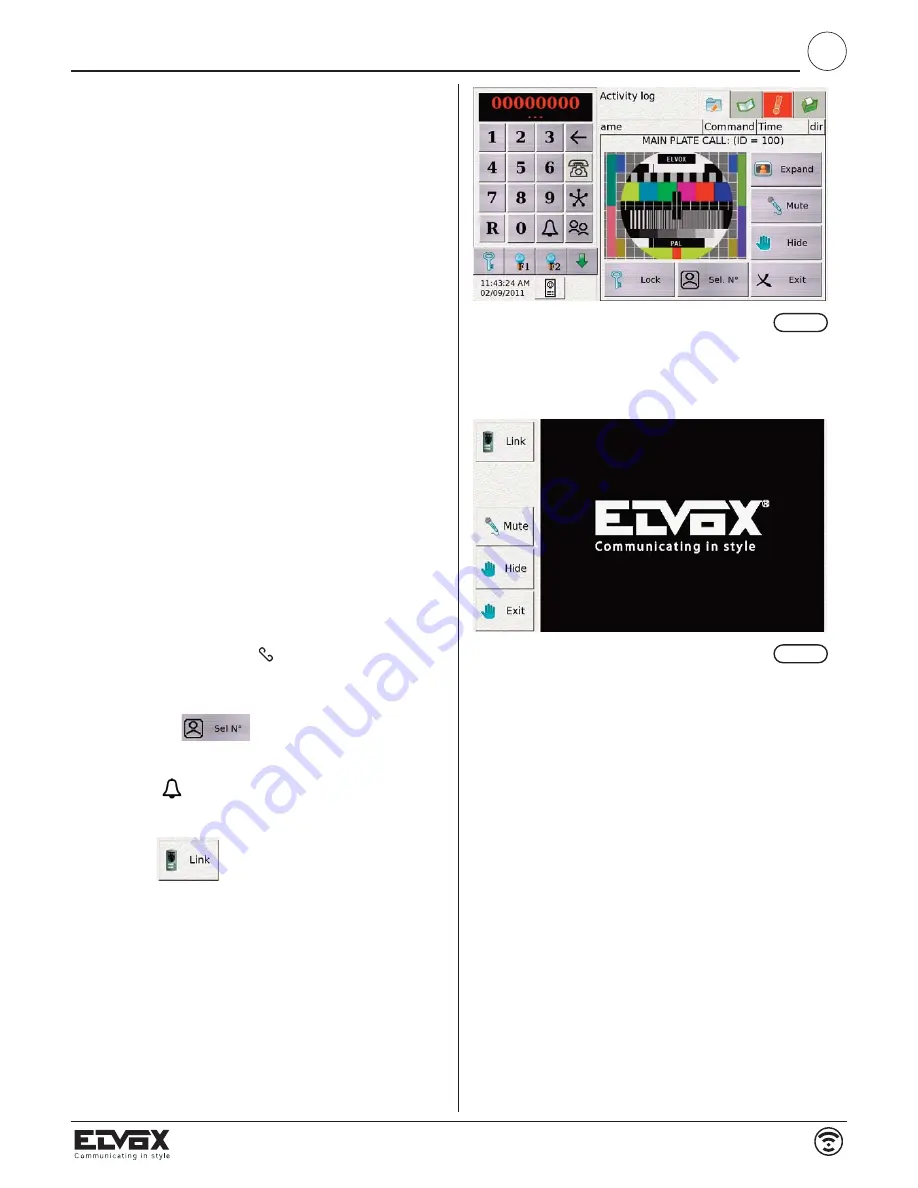
Fig. 13

Fig. 14

2) Internal operation:

all phases are activated and allowed by

the switchboard operator. 

To make a call from the video switchboard to one of the in-

ternal users, dial the user's number using the keypad and
press the bell key. 

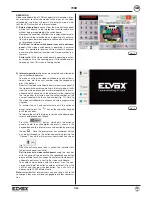
Direct call to video switchboard from main entrance panel: if

the video switchboard is operating in internal mode, all calls
from the main entrance panel are intercepted by the swit-
chboard which connects to the external station, displaying
the image from the station and the called number, or the
name associated with the called number (fig. 13). Calls to
the video switchboard are announced with a programmed
ringtone. 

To answer the call and communicate with the entrance

panel, simply press the “

” key on the capacitive keypad

or lift the handset. 

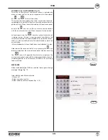
To forward the call to the internal user, the switchboard ope-

rator should proceed as follows: 

Press the “

” button  which puts the entrance

panel on hold, the called digibus address is shown in the
keypad box and this internal user can be called by pressing

the key 

. Once the internal user has answered, he/she

can be put through to the entrance panel by pressing the
“Connect” key on the internal user communication screen

(fig 14) 

When the entrance panel icon is yellow this indicates that

the entrance panel is on hold. 

Call from user to video switchboard: 

using the lock key

with the handset raised or with the speakerphone button
pressed (Wide Touch has a specific key for call to video swit-
chboard) a porter call is sent to the video switchboard.   

To enable communication with the internal user, the con-

cierge should dial the caller's number, or select it from the
calls list, and then press the bell button.  the calls list can
display up to 10,000 different calls. 

Note: 

remember that internal users can only send a call to the

concierge if they are not already engaged in another conversa-
tion.

GB

7/20

735B

Summary of Contents for 735B

Page 1: ...735 B0E RL 02 6 2012 GB INSTALLATION AND OPERATION MANUAL DIGIBUS WIDE TOUCH CONCIERGE STATION VIDEO PORTER SWITCHBOARD Art 735B Product is according to EC Directive 2004 108 CE 2006 95 CE and followi...

Page 2: ...ABS Interphone dimensions 89 x 222 x 200 mm Removable terminal blocks Monitor with 7 colour TFT LCD touch screen 16 9 aspect ratio Operating temperature from 0 C to 40 C Electronic ringtone Power sup...

Page 3: ...terminal F2 Auxiliary function 2 activation control terminal 4 Negative supply voltage terminal 5 12VDC supply voltage terminal R Terminal for connection of an additional bell I Monitor shutdown contr...

Page 4: ...archive monthly or daily monthly is the default setting in this section the video switchboard automatically creates a csv file which can be opened using Excel and which lists all calls or alarms that...

Page 5: ...and year Advanced setup Fig 7 8 always accessed by entering the password 123 and can be used to set a large number of pa rameters such as 1 configuration new password used to change the default passwo...

Page 6: ...essage for calls received from external entrance panels and the person making the call from the external panel can re cord an audio video message Remember to enable this function using key H 5 time sl...

Page 7: ...in internal mode all calls from the main entrance panel are intercepted by the swit chboard which connects to the external station displaying the image from the station and the called number or the na...

Page 8: ...s A and B by pressing the leave intercom calls key at this point hang up the video switchboard handset INTERCOM CALLS IN DIGIBUS SYSTEM MODE Intercom calls conference between users 1 To connect two us...

Page 9: ...warning sound is emitted on the voice line to indicate that the switchboard has joined the conver sation it is then possible to cut off communication or leave the conversation If the switchboard is i...

Page 10: ...esistance 100m 14 00 6 60 4 80 3 50 2 20 1 70 1 14 0 69 0 39 0 28 Comparative table of cross sections diameters resistances x 100m of commercially available conductors Conductors up to 50 m up to 100...

Page 11: ...D 4 5 V2 R V1 GND GND V1 V2 V3 GND V3 L P L P J1 D0 J1 D0 L P J1 D0 Mains F Art 6942 D0 D0 H Art 6582 Q Art 0170 051 D0 VIDEC DOOR ENTRY SYSTEM WITH THREE ENTRANCE PANELS TYPE 1286 POWER SUPPLY UNIT T...

Page 12: ...CH S F1 4 V 1 3 75 Ohm L M1 V2 I SR V1 VL F1 4 F2 CH V 3 1 M 5 8 6 4 4 R1 4 0 S1 15 R2 5 4 F2 3 PRI CH S F1 L P J1 D L P J1 D Cable riser see diagram si624 D D F Art 6942 F Art 6942 Cable riser see di...

Page 13: ...F1 4 R1 4 0 S1 15 R2 5 4 F2 3 PRI CH S F1 R1 4 R2 15 O 4 S1 4 5 3 F1 F2 PRI CH S 75ohm L P L P J1 D0 J1 D0 SR V 1 4 3 5 L 4 3 1 V S T F1 6 CH I 8 1 3 F2 GND 4 5 V2 R V1 GND GND V1 V2 V3 GND V3 Cable r...

Page 14: ...m 4 T2 5 6S T1 2 1 A T4 C B VIDEO T3 6P B A C 12 CH 2 E 1 M E FP I PRI U A C B FP E M 1 E 2 CH 12 A C B FP E M 1 E 2 CH 12 K K K K J Art 692C A Petrarca series interphone type 6209 B Monitor type 68MV...

Page 15: ...K K K K 15 20 D I A G R A M CABLE RISER WITH INTERFACE TYPE 69DM SEPARATORS TYPE 692S POWER SUPPLY UNIT TYPE 6922 DISTRIBUTOR TYPE 692D MO NITOR TYPE 7311 AND POWER SUPPLY UNIT TYPE 6923 REF SI627 A...

Page 16: ...5 12 6 11 1 4 3 P L J1 D P L J1 D 75ohm 75ohm To switchboard type 735B SYSTEM FOR PANEL 1 WITH ENTRANCE PANELS TYPE 1286 POWER SUPPLY TYPE 6948 MONITOR TYPE 7214 TYPE 6614 AND INTER PHONE TYPE 6204 RE...

Page 17: ...V1 GND GND V1 V2 V3 GND V3 S T F1 6 CH I 8 1 3 F2 GND 4 5 V2 R V1 GND GND V1 V2 V3 GND V3 CONNECTION VARIANT WITH ADDITIONAL LOCK ON 735B WIDE TOUCH CONCIERGE STATION REF SI628 Mains F Art 6942 Mains...

Page 18: ...18 20 NOTE...

Page 19: ...o avoid the possibility of hurting yourself this unit must be fixed to the wall according to the installation instructions This leaflet must always be enclosed with the equipment Directive 2002 96 EC...

Page 20: ...lan SALES OFFICES IN ITALY INTERNATIONAL SALES OFFICES ELVOX Costruzioni elettroniche S p A ITALY Via Pontarola 14 a 35011 Campodarsego Padova Tel 049 9202511 Fax 049 9202603 info elvox com Telefax Ex...

Reviews: