GB
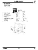
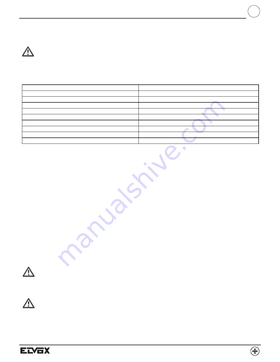
GENERAL CHARACTERISTICS
SINGLE-PHASE SUPPLY VOLTAGE
230 V AC +6% -10 %
FREQUENCY
50 Hz
MOTOR SUPPLY VOLTAGE
230 V AC +6% -10 %
MOTOR MAXIMUM POWER
300 W
VOLTAGE FOR EXTERNAL DEVICES
24 V DC +15% -10%
MAXIMUM ABSORBED POWER EXT. DEV.
20 W
EQUIPMENT AND ACCESSORIES PROTECTION
T1 A time-delay fuse (F1)
MOTOR PROTECTION
5 A fuse (F2)
TEMPERATURE RANGE
- 20 to +70 °C inside enclosure
PROTECTION RATING
IP55
MECHANICAL INSTALLATION
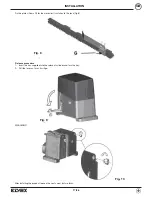
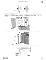
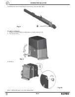
For correct installation, fix the box in a secure place where it is protected from the weather.
ELECTRICAL INSTALLATION
The equipment is installed in the electrical housing.
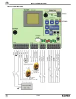
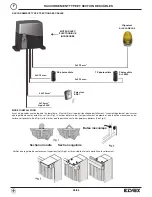
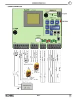
1 - After inserting the actuator, make the connections by following the operations indicated in Fig. 1.
(for actuators with Encoder, connect the cable to connector CN6).
2 - Select short routes for the connections with multicore cable of the type prescribed by current standards.
3 - The gate’s earthing device must conform to current standards.
The manufacturer accepts no liability for damage arising from negligence in this respect.
4 - In accordance with European safety standards, it is recommended that a mains two-pole switch is installed in order to be able to di-
sconnect the power supply before carrying out maintenance on the gate and to disconnect the terminal of the card power supplies.
5 - Check that each individual device (photocells, key selector, etc.) works effectively and efficiently.
6 -
Apply adequate supplementary safety measures to the automatic system where required.
Fitting/replacing the card
In case of REPLACEMENT, it is necessary to:
- IMPORTANT! Switch off the power supply.
- Disconnect all connections.
- Remove the card by undoing the fixing screws.
- Position the new card and fix in place.
- Restore the connections.
- Restore the power supply, reprogram and save the radio controls.
Electrical connections and hook-up to the mains supply
The N.C. contacts must be jumpered to earth (GND terminal) when not used. Otherwise the automatic gate system will NOT function!
If a N.O. input is closed, or a N.C. input is open, the PROG-DL9 LED flashes at high frequency.
START-UP
Before starting up the system for the first time, make sure that no-one is in the vicinity of the automatic gate.
When the gate is closed, the N.C. closure limit contact (terminal no. 15) must be open (green LED DL8 off). Conversely, if the N.C. ope-
ning limit contact is active (terminal no. 13, green LED DL7 off), the cables for terminal no. 13 and terminal no. 15 should be inverted, as
should the cables for the opening (terminal no. 7) and closing (terminal no. 8) phases.
After completing and checking the electrical connections, power up the equipment and immediately execute TRAVEL PATH LEARNING
(see Programming paragraph).
GENERAL CHARACTERISTICS
The EC40 equipment has been designed to control the operation of 230 V AC electromechanical actuators for the automation of swing gates.
Any other use is to be considered improper and therefore hazardous.
It is prohibited to use the product for an improper purpose or for any purpose other than its intended use.
It is prohibited to tamper with or modify the product.
The manufacturer assumes no liability for failure to comply with these requirements.
Technical data
Before installing the product, check that the temperature limits indicated are suitable for the installation environment.
19/36


