background image

   15

K40515.E

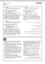
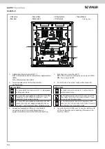
2 - 

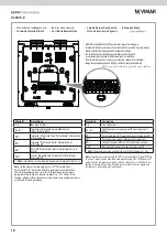
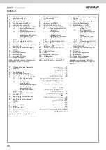
Terminaison Bus Due Fili Plus (Dip-Switch de configuration)

3 - 

Connecteur (réceptacle) USB type C : interface de 

connexion à un ordinateur pour la configuration et/ou la 

mise à jour firmware à l’aide du logiciel SaveProg.

1 - 

Validation alimentation via BUS (*)

 OFF

 = Alimentation supplémentaire (6923).

 ON

 = Alimentation via BUS.

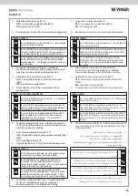
TABLEAU SWITCH

A

 = Le câble du BUS arrive aux bornes 1, 2 puis se dirige 

vers un autre poste intérieur

B

 = Le câble BUS avec une impédance caractéristique de 

100 ohms (câble Elvox 732I ou 732H) arrive aux bornes 1, 

2 et la colonne montante s'arrête au poste intérieur

C

 = Le câble BUS avec une impédance caractéristique 

de 50 ohms (câble cat. 5 ou cat. 6 à paires torsadées) 

arrive aux bornes 1, 2 et la colonne montante s'arrête au 

poste intérieur

2 - 

Bus-Abschluss Due Fili Plus (Dip-Schalter für Konfiguration)

3 - 

USB-Stecker Typ C (Receptacle): Schnittstelle zum 

Anschluss an einen PC für die Konfiguration und/oder 

Firmwareaktualisierung mittels der Software SaveProg.

1 - 

Freigabe der Versorgung über BUS (*)

 OFF

 = Versorgung über Zusatznetzteil (6923).

 ON

 = Versorgung über BUS.

SCHALTERTABELLE

A

 = Das BUS-Kabel tritt in die Klemmen 1, 2 ein und führt zu 

einer anderen Innenstelle

B

 = Das BUS-Kabel mit typischer Impedanz 100 Ohm (Elvox 

Kabel 732I oder 732H) tritt in die Klemmen 1, 2 ein und die 

Steigleitung endet an der Innenstelle

C

 = Das BUS-Kabel mit typischer Impedanz 50 Ohm 

(Kabel Cat.5 oder Cat.6 mit gepaarten Doppeladern) tritt 

in die Klemmen 1, 2 ein und die Steigleitung endet an der 

Innenstelle

2 - 

Terminación Bus Due Fili Plus (conmutador DIP de 

configuración)

3 - 

Conector (receptacle) USB tipo C: interfaz de conexión a 

un PC para la configuración y/o actualización del firmware 

mediante el software SaveProg.

1 - 

Habilitación de la alimentación por BUS (*)

 OFF

 = Alimentación mediante alimentador adicional 

(6923).

 ON

 = Alimentación mediante BUS.

TABLA DE LOS CONMUTADORES DIP

A

 = El cable del BUS entra en los bornes 1, 2 y continúa 

hasta otro aparato interno

B

 = El cable BUS con impedancia característica de 100 

ohmios (cable Elvox 732I o 732H) entra en los bornes 1, 2 

y el montante termina en el aparato interno

C

 = El cable BUS con impedancia característica de 50 

ohmios (cable Cat.5 o Cat.6 con los cables de pares 

acoplados) entra en los bornes 1, 2 y el montante 

termina en el aparato interno

2 - 

Terminação Bus Due Fili Plus (Dip Switch de configuração)

3 - 

Conector (receptacle) USB type C: interface de ligação a um PC 

para a configuração e/ou atualização do firmware através do 

software SaveProg.

1 - 

Habilitação da alimentação a partir do BUS (*)

 OFF

 = Alimentação através de alimentador suplementar 

(6923).

 ON

 = Alimentação através de BUS.

TABELA SWITCH

A

 = O cabo do BUS entra nos terminais 1, 2 e continua para 

um outro posto interno

B

 = O cabo BUS com impedância característica de 100 

Ohm (cabo Elvox 732I ou 732H) entra nos terminais 1, 2 e a 

coluna montante para no posto interno

C

 = O cabo BUS com impedância característica de 50 Ohm 

(cabo Cat.5 ou Cat.6 com os pares entrançados acoplados) 

entra nos terminais 1, 2 e a coluna montante para no posto 

interno

2 - 

Τερματισμός Bus Due Fili Plus (Dip Switch διαμόρφωσης)

3 - 

Συνδετήρας (υποδοχή) USB τύπου C: interface σύνδεσης 

σε Η/Υ για τη διαμόρφωση ή/και την ενημέρωση 

υλικολογισμικού μέσω του λογισμικού SaveProg.

1 - 

Ενεργοποίηση τροφοδοσίας από BUS (*)

 OFF

 = Τροφοδοσία μέσω συμπληρωματικού τροφοδοτικού 

(6923).

 ON

 = Τροφοδοσία μέσω BUS.

ΠΙΝΑΚΑΣ SWITCH

A

 = Το καλώδιο του BUS εισάγεται στις επαφές κλέμας 1, 

2 και συνεχίζει προς άλλο εσωτερικό σταθμό

B

 = Το καλώδιο BUS με χαρακτηριστική σύνθετη 

αντίσταση 100 Ohm (καλώδιο Elvox 732I ή 732H) 

εισάγεται στις επαφές κλέμας 1, 2 και η κεντρική γραμμή 

τερματίζεται στον εσωτερικό σταθμό

Γ

 = Το καλώδιο BUS με χαρακτηριστική σύνθετη 

αντίσταση 50 Ohm (καλώδιο κατ.5 ή κατ.6 με τα ζεύγη 

συνδεδεμένα) εισάγεται στις επαφές κλέμας 1, 2 και η 

κεντρική γραμμή τερματίζεται στον εσωτερικό σταθμό

 )Dip switch( ةجودزلما يطخلا ليدبتلا ةمزح حاتفم( Bus Due Fili Plus ءاهنإ

 -  2

)ةئيهتلاو طبضلاب صاخلا

 طبضل تارتويبموكلا دحأب ليصوتلا مادختسا ةهجاو :Cةيعونلا USB )سبقم( لصوملا

 -  3

.SaveProg جمانبرلا للاخ نم تباثلا مكحتلا جمانرب ثيدحت وأ/و ةئيهتو

)*( BUS لقان للاخ نم ةيليغشتلا ةيذغتلا ليعفت

 -  1

.)6923( يفاضإ ةقاط دوزم للاخ نم ةيليغشت ةيذغت = 

)فاقيإ( OFF


.BUS لقان للاخ نم ةيليغشت ةيذغت = 

)ليغشت( ON


حيتافلما لودج

 ناكم ىتح لصاويو 2و 1 ليصوتلا فيرط في لخدي BUS لقانلا لباك ناك اذإ = 

A

رخآ ليخاد

 وأ Elvox 732I لباك( موأ 100 ةزيمم ةيئابرهك ةقواعبم BUS لقانلا لباك = 

B

ليخادلا ناكلما في فقوتي تيبثتلا لماحو 2و 1 ليصوتلا فيرط في لخدي )732H

 Cat.6 وأ Cat.5 لباك( موأ 50 ةزيمم ةيئابرهك ةقواعبم BUS لقانلا لباك = 

C

 تيبثتلا لماحو 2و 1 ليصوتلا فيرط في لخدي )ةلوصوم ةلودجم ةجودزم كلاسأب

ليخادلا ناكلما في فقوتي

Summary of Contents for K40515.E

Page 1: ...rtero Due Fili Plus unifamiliar Kit de videoporteiro Due Fili Plus monofamiliar Due Fili Plus Due Fili Plus PRI 1 2 B1 B2 6922 1 POWER SUPPLY UNIT PRI 110 240V 1 0 6A 50 60Hz 1 2 B1 B2 28V 1A CONT 0 6...

Page 2: ...raccordement 35 Conformit aux normes et recommandations 38 Inhalt Set Videohaustelefon K40515 E 3 Verpackungsinhalt 4 Videohaustelefon 40515 5 Klingeltableau 40151 23 Elektronikeinheit 40135 24 Netzte...

Page 3: ...me Due Fili Plus disponibles sur le site www vimar com Set Freisprech Farb Videohaustelefon Due Fili Plus f r Einfamilienh user mit 1wei emFreisprech VideohaustelefonTAB5SUP2F Wi Fi40507mit integriert...

Page 4: ...Sachet avec deux vis de fixation et goujons pourune ventuellefixationensaillie Unit lectroniqueaudio vid o40135 Alimentationsyst meDueFiliPlus6922 1 Alimentation 2calottescache bornes Sachet avec 4 v...

Page 5: ...r rio Si consiglia di installare il dispositivo facendo attenzione a non esporlo a fonti dirette di illuminazione in modo da evitare fastidiosi fenomeni di riflessione sulla superficie dello schermo L...

Page 6: ...Montaje Instala o Installazioneapareteconfissaggiosuscatola3moduliverticale Vimar71303 Exampleoffixingonverticalmountingboxwith3modules Vimar71303 Installationensaillieavecfixationsurbo te3modulesver...

Page 7: ...eronde Vimar71701 Bo terectangulaire3modules Vimar71303 V71703 poseverticaleouhorizontale Bo tecarr estandardbritannique Bo tes720E 7249 avecaccessoire40196 Bo tes6149 V71318 V71718 avecaccessoire755S...

Page 8: ...Desmontaje Desmontagem 6 40590 Vimar71701 3 Vimar71303 V71703 720E 7249 40196 6149 V71318 V71718 755S 40595 6 40590 Vimar 71701 Vimar 71303 V71703 3 British 40196 720E 7249 755S V71318 V71718 6149 40...

Page 9: ...BUS bornes 1 2 tension nominale 28 Vcc 5 16 8 800x480 15 9 bus 20dBm Wi Fi 802 11 b g n 2 4 GHz 2400 2483 5 MHz RF 100 mW 20 dBm 55 mA 420 mA A1 IP30 5 40 C 10 80 6923 E E BUS 1 2 28 V DC 5 Display mi...

Page 10: ...backlighting from the user setting Vista frontale Front view Vue de face Frontansicht Vista frontal Vista frontal 1 Microphone 2 cran tactile capacitif 5 pouces 16 8 millions de couleurs r solution 8...

Page 11: ...ettronici pu compromettere la qualit del suono percepito sull apparecchio acustico Audio frequency function for hearing aids Teleloop The video entryphone can be used by people wearing hearing aids Fo...

Page 12: ...ia e Apertura Porta possono essere modificate tramite programmazione Per le funzioni attivabili fare riferimento al manuale uso e configurazione e al software di configurazione Keys Default functions...

Page 13: ...a programaci n Para las funciones activables consulte el manual de uso y configuraci n y el software de configuraci n 7 8 9 10 2 fili Aux 1 11 Tasten Standardfunktionen 7 Sprechen H ren Anruf entgegen...

Page 14: ...OFF Alimentazione tramite alimentatore supplementare 6923 ON Alimentazione tramite BUS 2 Due Fili Plus Bus termination Configuration Dip Switch SWITCH TABLE A the BUS cable enters terminals 1 2 and co...

Page 15: ...guraci n 3 Conector receptacle USB tipo C interfaz de conexi n a un PC para la configuraci n y o actualizaci n del firmware mediante el software SaveProg 1 Habilitaci n de la alimentaci n por BUS OFF...

Page 16: ...l utilisationsansalimentationsuppl mentaire mettreleBUSPOWERsurON r glaged usine Pourl utilisationavecunealimentationsuppl mentaire ilconvientdemettreleBUSPOWERsur OFFpour viterdesurchargerl installat...

Page 17: ...15 InterruptorBUSPOWER Paraumautiliza osemalimentadorsuplementar posicioneoBUSPOWERemON factorydefault Paraumautiliza ocomalimentadorsuplementar prefer velposicionaroBUSPOWERemOFF para evitarumasobrec...

Page 18: ...rta possono essere modificate tramite programmazione L uscita CH Ripetizione di chiamata programmabile Open Collector default o 12V 100mA Per le funzioni attivabili fare riferimento al manuale uso e c...

Page 19: ...e Konfigurationssoftware verwiesen Bornes Descripci n 1 2 Bus Due Fili Plus E E Entrada alimentaci n suplementaria alimentador 6923 FP Entrada Llamada fuera puerta local referencia al borne M IN Entra...

Page 20: ...che une page de bienvenue Le wizard de configuration d marrera automatiquement au bout de 3 secondes ou apr s avoir touch un point quelconque de l cran BeimerstenStartdesGer tserscheinteineWillkommens...

Page 21: ...ingiscomplete thedevicedisplaysthehomescreen Une fois la proc dure automatique termin e la page finale reste affich e 6 secondes puis le dispositif red marre Lorsque le dispositif a red marr il affich...

Page 22: ...arque liminer les connexions au BUS et l alimentation suppl mentaire avant de brancher le dispositif l ordinateur travers la prise USB Des syst mes de s curit emp chent l ex cution d un firmware non a...

Page 23: ...oserseanormaemvigorfordiferente 38 mm 12 mm Targa 40151 Entrance panel 40151 Plaque 40151 Klingeltableau 40151 Placa 40151 Botoneira 40151 40151 40151 Gradodiprotezione IP54 Gradodiprotezionecontrogl...

Page 24: ...riel lectriqueenvigueurdanslepaysconcern Proc der l installationde sortequelesujetquidoit trefilm soit clair defaceetnonencontre jour loind autressourceslumineuses tellesquedesr verb res despharesd au...

Page 25: ...pulsador P2 paraplaca40152 Liga odaunidadeeletr nica40135complacadobot oP2 parabotoneira40152 40135 P2 40152 40152 P2 40135 Scatoladautilizzaresoloperinstallazionedaesternoparete Boxtobeusedonlyforext...

Page 26: ...26 K40515 E 6 5 3 2 1 1 VIMAR 2 3 4 5 6...

Page 27: ...erence for terminal CA CA Door lock release control door open signal sensor see Dip Switch table switch position 3 B1 B2 BUS S S 12VDC lock output 7 Reset button RST 8 Connector for programming via so...

Page 28: ...S Sa da do trinco 12Vcc 7 Tecla reset RST 8 Conector para programa o a partir do software SER 9 Conector para tecla de chamada P2 LED P2 10 Altifalante 11 Volume do microfone 12 Balanceamento 13 Volu...

Page 29: ...erderKonfigurationmittelsDip SchalternVorrang Nota en las instalaciones con varias placas es necesario definir una placa Master y las dem s como Slave La programaci n por ordenador o SaveProg prevalec...

Page 30: ...o 30 40 50 60 70 80 90 100 110 120 130 140 150 160 170 180 Accensione On Allumage Einschaltung Conexi n Acendimento 5 6 8 10 11 13 15 16 18 20 21 23 25 26 28 30 Risposta Response R ponse Antwort Resp...

Page 31: ...i n del tiempo de conversaci n autoencendido respuesta Regula o do tempo de conversa o autoacendimento resposta Rimappatura tasti P1 o P2 Remapping buttons P1 or P2 Remappage des touches P1 ou P2 Tast...

Page 32: ...224Vcc 9W 16dBm 100Ohm 25 55 C C maraCMOS consalidaPAL CVBS Resoluci n380l neasTV ngulosdevisual100 82 horizontal vertical Iluminaci nm nima1 0lux Alimentaci natrav sdelosbornesB1 B2 Absorci nenstand...

Page 33: ...17 5 mm module dimensions 140 x 115 x 65mm Protection degre IP30 for installation in consumer units with DIN rail 60715 TH35 Installation for CAT II overvoltage cat egory Class II symbol Caracter stic...

Page 34: ...secured to the wall as described in the installation instruc tions Above the power supply there must be a bipolar circuit breaker that is easily accessible with a contact gap of at least 3 mm Normas...

Page 35: ...K B2 B1 CA CA E E S S 2 1 PRI B2 2 1 B1 E 2 E 1 FP IN M CH B 1 2 ON B Videocitofono 40515 C Targa videocitofonica 40151 D Unit elettronica 40135 F Alimentatore di sistema K Pulsante di chiamata fuori...

Page 36: ...C NO NO NO NC E 2 E 1 FP IN M CH E 2 E 1 FP IN M CH E 2 E 1 FP IN M CH E 2 E 1 FP IN M CH E 2 E 1 FP IN M CH E 2 E 1 FP IN M CH E 2 E 1 FP IN M CH E 2 E 1 FP IN M CH E 2 E 1 FP IN M CH E 2 E 1 FP IN M...

Page 37: ...onfigurazione disponibile solo se il dispositivo alimentato da alimentatore supplementare 12Voutput 100mA Configurationonlyavailableifthedeviceispoweredbyanadditionalpowersupplyunit Sortie 12V 100 mA...

Page 38: ...DirettivaRoHS NormeEN62368 1 EN301489 17 EN300328 EN 62311 EN55032 EN55035 ENIEC63000 RegolamentoREACh UE n 1907 2006 art 33Il prodottopotrebbeconteneretraccedipiombo VimarSpAdichiarachel apparecchia...

Page 39: ...amenteaodistribuidoroaparelhoquesepretendeeliminar aquandodacompradeumnovo equipamentodetipoequivalente Nosdistribuidoresdeprodutoseletr nicoscomumasuperf ciedevendadepelomenos400m2 aindaposs velentre...

Page 40: ...49401634A0 01 2104 Viale Vicenza 14 36063 Marostica VI Italy www vimar com...

Reviews: