background image

10

measurement result is indicated via the LEDs immediately after the measure

-

ment and is output at the analogue and floating contacts respectively. 

Measuring cycle

PIN1

PIN2

PIN3

Quick (every 2 seconds)

X (any)

X (any)

0 (OFF)

Slow (every 20 seconds)

X (any)

X (any)

1 (ON)

    Each measurement requires energy. In battery mode, short intervals 

between the measurements significantly reduce battery life!

6.4. Fitted lock 

Integral disconnection in the unique fitted lock enables the measurement 

probe to be removed or replaced without any water leaking out and causing 

the pressure in the system to drop. The fitted lock has a 1" female thread on 

both sides and causes virtually no pressure drop.

7. Maintenance

7.1. Battery replacement

When the orange and red LEDs flash si

-

multaneously, the battery needs replacing. 

Undo the two screws in the transparent cov

-

er, lift off the cover, carefully raise the circuit 

board and insert the new battery (PURO

-

TAP® i-control-21, replacement battery part 

no. 102373). Make sure the cover seal is 

seated properly. Refit the cover and secure 

with the screws. Check the device is    


working correctly.

Summary of Contents for PUROTAP i-control-21

Page 1: ...www elysator com Installation Function Operation Maintenance Operating instructions PUROTAP i control 21s...

Page 2: ......

Page 3: ...Specification 4 1 Device description 6 4 2 Dimensions 7 4 3 Performance data 7 5 Installation 8 6 Operation 6 1 Switching on and off 9 6 2 Adjusting the operating temperature 9 6 3 Intervals between...

Page 4: ...4 1 Safety instructions Not drinking water Maximum 60 C Maximum 4 bar pressure Dust proof and protected against water jets from any angle 4 bar IP65 Never dispose of the device in household waste...

Page 5: ...system The water quality on site is indicated by a flashing LED and can also be transmitted to an alert system via the floating contact An external analogue indicator can also be connected 3 Standard...

Page 6: ...coaxial power connector part no 102384 max 30V AC DC 2A 6 Connection for analogue output 4 20 mA max 24 V DC coaxial power connector part no 102384 max 24V DC _ 7 Connection for external power supply...

Page 7: ...service function 10 Insulation EPP 11 Connections on both sides 1 female 4 2 Dimensions 125mm 98mm 90mm 1 0 0 m m 4 3 Performance data PUROTAP i control 21 Display 3 LED green Good 0 to 200 S cm Disp...

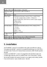
Page 8: ...f pro tection IP 65 Power supply int Lithium battery 3 6 V 1200 mAh ER14250 Power supply ext Via micro USB 5 V DC 0 5 A max 5 Installation The PUROTAP i control 21 is installed in the water circuit fl...

Page 9: ...ctivity measurement correctly the maximum anticipated operating temperature of the system must be set PIN setting Max operating temperature PIN 1 PIN 2 PIN 3 25 C 0 OFF 0 OFF x any 20 C 0 OFF 1 ON x a...

Page 10: ...enables the measurement probe to be removed or replaced without any water leaking out and causing the pressure in the system to drop The fitted lock has a 1 female thread on both sides and causes virt...

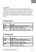
Page 11: ...ld it down for more than 4 seconds and then release it All 3 LEDs should flash briefly once the device has now been recal ibrated 8 Spare parts Item no Designation 102 373 PUROTAP i control 21 replace...

Reviews: