background image

6

4. Specification

4.1. Device description


1  Casing

2  Union nut (¾" female thread)

3  Flat gasket

4  Measuring probes

5   Connection for floating switching contact


(max. 30 V 2 A), 


coaxial power connector part no. 102384


max. 30V AC/DC, 2A

6   Connection for analogue output 


(4-20 mA, max. 24 V DC), 


coaxial power connector part no. 102384


max. 24V DC

+

_

7  Connection for external power supply


  (5 V DC, 0.5 A), micro USB connector

Front view

Conductivity

Green flashing LED (good)

Yellow flashing LED (caution required)

Red flashing LED (check required)

4

3

2

1

5

6

7

Summary of Contents for PUROTAP i-control-21

Page 1: ...www elysator com Installation Function Operation Maintenance Operating instructions PUROTAP i control 21s...

Page 2: ......

Page 3: ...Specification 4 1 Device description 6 4 2 Dimensions 7 4 3 Performance data 7 5 Installation 8 6 Operation 6 1 Switching on and off 9 6 2 Adjusting the operating temperature 9 6 3 Intervals between...

Page 4: ...4 1 Safety instructions Not drinking water Maximum 60 C Maximum 4 bar pressure Dust proof and protected against water jets from any angle 4 bar IP65 Never dispose of the device in household waste...

Page 5: ...system The water quality on site is indicated by a flashing LED and can also be transmitted to an alert system via the floating contact An external analogue indicator can also be connected 3 Standard...

Page 6: ...coaxial power connector part no 102384 max 30V AC DC 2A 6 Connection for analogue output 4 20 mA max 24 V DC coaxial power connector part no 102384 max 24V DC _ 7 Connection for external power supply...

Page 7: ...service function 10 Insulation EPP 11 Connections on both sides 1 female 4 2 Dimensions 125mm 98mm 90mm 1 0 0 m m 4 3 Performance data PUROTAP i control 21 Display 3 LED green Good 0 to 200 S cm Disp...

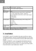
Page 8: ...f pro tection IP 65 Power supply int Lithium battery 3 6 V 1200 mAh ER14250 Power supply ext Via micro USB 5 V DC 0 5 A max 5 Installation The PUROTAP i control 21 is installed in the water circuit fl...

Page 9: ...ctivity measurement correctly the maximum anticipated operating temperature of the system must be set PIN setting Max operating temperature PIN 1 PIN 2 PIN 3 25 C 0 OFF 0 OFF x any 20 C 0 OFF 1 ON x a...

Page 10: ...enables the measurement probe to be removed or replaced without any water leaking out and causing the pressure in the system to drop The fitted lock has a 1 female thread on both sides and causes virt...

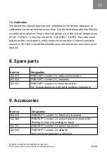
Page 11: ...ld it down for more than 4 seconds and then release it All 3 LEDs should flash briefly once the device has now been recal ibrated 8 Spare parts Item no Designation 102 373 PUROTAP i control 21 replace...

Reviews: