15
Chapter 2 Connecting Peripherals
2.8 Making Connections
The following sections tell how to make each connection. In most cases,
you will simply need to connect a standard cable. All of the connector pin
assignments are shown in Appendix C.
2.9 CPU Fan power supply connector (CN1)
Provides power supply to CPU cooling fan. Only present when +5 V and
+12 V power is supplied to the board.
2.10 Serial ports (CN2, CN3, CN4)
The PCM-9340 offers four serial ports: three RS-232 (COM 1, 3, 4) and
one RS-232/422/485 (COM 2). These ports allow you to connect to any
serial device (a mouse, a printer, etc.) or to a communication network.
2.10.1 COM3/COM4 RS-232 port (CN2)
The COM3/COM4 series port, consists of 20 pin dual-in-line, male
header.
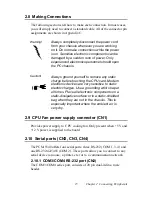
Warning!
Always completely disconnect the power cord
from your chassis whenever you are working
on it. Do not make connections while the power
is on. Sensitive electronic components can be
damaged by a sudden rush of power. Only
experienced electronics personnel should open
the PC chassis.
Caution!
Always ground yourself to remove any static
charge before touching the CPU card. Modern
electronic devices are very sensitive to static
electric charges. Use a grounding wrist strap at
all times. Place all electronic components on a
static-dissipative surface or in a static-shielded
bag when they are not in the chassis. This is
especially important where the ambient air is
very dry.
Summary of Contents for PCM-9340F-0CA1
Page 1: ...i PCM 9340 ISA STPC Elite 133 SBC with CPU 32MB SDRAM VGA LCD LAN DOC PC104 Users Manual...
Page 4: ...PCM 9340 User s Manual iv...
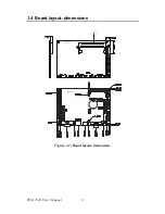
Page 14: ...PCM 9340 User s Manual 6 1 4 Board layout dimensions Figure 1 1 Board layout dimensions...
Page 48: ...PCM 9340 User s Manual 40 2 Select the Settings tab then click the Advanced Properties but ton...
Page 53: ...45 Chapter 4 SVGA Setup 2 Select Adapter then Change...
Page 58: ...PCM 9340 User s Manual 50 2 Choose the Settings tab and press the Display Type button...
Page 59: ...51 Chapter 4 SVGA Setup 3 Press the Change button...
Page 67: ...59 Chapter 5 PCI Bus Ethernet Interface 3 Select the Driver tab then click Update Driver...
Page 72: ...PCM 9340 User s Manual 64 3 Click on Properties select the Driver tab then Update Driver...
Page 76: ...PCM 9340 User s Manual 68 10 Reboot the system...
Page 78: ...PCM 9340 User s Manual 70 3 Click Have Disk 4 Type in the path then click OK...
Page 80: ...PCM 9340 User s Manual 72...
Page 88: ...TPC 642 User s Manual 80...
Page 91: ...83 Appx B Figure B 1 PC 104 module mounting diagram PCM 9340...
Page 92: ...PCM 9340 User s Manual 84 Figure B 2 PC 104 module dimensions mm 0 1...
Page 115: ...107 Appx E E Mechanical Drawings Appendix...
Page 117: ...109 Appx E Figure E 2 PCM 9340 Mechanical Drawing solder side...
Page 118: ...PCM 9340 User s Manual 110...


