Table of Contents
vii
Chapter
4 SVGA Setup....................................................37
4.1
Introduction ..................................................................... 38
4.1.1
Chipset .......................................................................... 38
4.1.2
Display memory............................................................ 38
4.2
Installation of the SVGA Driver ..................................... 38
4.2.1
Installation for Windows 95 ......................................... 39
4.2.2
Installation for Windows 98 ......................................... 44
4.2.3
Installation for Windows NT ........................................ 49
4.3
Further Information ......................................................... 54
Chapter
5 PCI Bus Ethernet Interface...........................55
5.1
Introduction ..................................................................... 56
5.2
Ethernet Driver Installation............................................. 56
5.2.1
Installation for Windows 95 ......................................... 57
5.2.2
Installation for Windows 98 ......................................... 62
5.2.3
Installation for Windows NT ........................................ 69
5.3
Further information ......................................................... 71
Chapter
6 Audio Setup.....................................................73
6.1
Introduction ..................................................................... 74
6.2
Audio Driver Installation ................................................ 74
6.2.1
Installation for Windows 95/98/NT.............................. 75
Appendix A Programming the Watchdog Timer .............77
A.1
Supported Input Timing Modes ...................................... 78
Appendix B Installing PC/104 Modules ............................81
B.1
Installing PC/104 Modules.............................................. 82
Figure B.1:PC/104 module mounting diagram............. 83
Figure B.2:PC/104 module dimensions (mm) (±0.1) ... 84
Appendix C Pin Assignments .............................................85
C.1
CPU fan power connector (CN1) .................................... 86
C.2
COM 3, COM 4 connector (CN2)................................... 86
C.3
COM 2 connector (CN3)................................................. 87
C.4
COM 1 RS-232 connector (CN4).................................... 87
C.5
PC/104 Connector (CN5) ................................................ 88
C.6
Ethernet 10/100Base-T Connector (CN6)....................... 90
C.7
Keyboard and PS/2 Mouse Connector (CN7) ................. 90
C.8
IR Connector (CN8) ........................................................ 91
C.9
IDE Hard Drive Connector (CN9) .................................. 92
C.10
CRT Display Connector (CN10)..................................... 93
C.11
Audio Connector (optional) (CN11) ............................... 93
C.12
LCD Inverter Backlight Connector (CN12).................... 94
C.13
ATX Power Feature Connector (CN13).......................... 94
C.14
Floppy Disk Drive Connector (CN14) ............................ 95
Summary of Contents for PCM-9340F-0CA1
Page 1: ...i PCM 9340 ISA STPC Elite 133 SBC with CPU 32MB SDRAM VGA LCD LAN DOC PC104 Users Manual...
Page 4: ...PCM 9340 User s Manual iv...
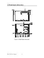
Page 14: ...PCM 9340 User s Manual 6 1 4 Board layout dimensions Figure 1 1 Board layout dimensions...
Page 48: ...PCM 9340 User s Manual 40 2 Select the Settings tab then click the Advanced Properties but ton...
Page 53: ...45 Chapter 4 SVGA Setup 2 Select Adapter then Change...
Page 58: ...PCM 9340 User s Manual 50 2 Choose the Settings tab and press the Display Type button...
Page 59: ...51 Chapter 4 SVGA Setup 3 Press the Change button...
Page 67: ...59 Chapter 5 PCI Bus Ethernet Interface 3 Select the Driver tab then click Update Driver...
Page 72: ...PCM 9340 User s Manual 64 3 Click on Properties select the Driver tab then Update Driver...
Page 76: ...PCM 9340 User s Manual 68 10 Reboot the system...
Page 78: ...PCM 9340 User s Manual 70 3 Click Have Disk 4 Type in the path then click OK...
Page 80: ...PCM 9340 User s Manual 72...
Page 88: ...TPC 642 User s Manual 80...
Page 91: ...83 Appx B Figure B 1 PC 104 module mounting diagram PCM 9340...
Page 92: ...PCM 9340 User s Manual 84 Figure B 2 PC 104 module dimensions mm 0 1...
Page 115: ...107 Appx E E Mechanical Drawings Appendix...
Page 117: ...109 Appx E Figure E 2 PCM 9340 Mechanical Drawing solder side...
Page 118: ...PCM 9340 User s Manual 110...


