Jumper and Connector Locations
5-3
Jumper and Connector Locations
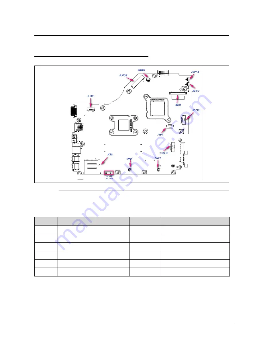
Mainboard Jumper and Connector Locations
0
Figure 5-1.
Mainboard Top
Table 5-1.
Mainboard Top
Item
Description
Item
Description
JLVDS1
Connect to LED / CCFL Panel
JCR1
Connector of 2 in 1 Card Reader
JSPK1
Connect to Right Speaker
JLED1
Connect to Power board (with FFC)
JSPK2
Connect to Left Speaker
JMIC2
Connect to Internal MIC
JKB1
Connect to Keyboard
SW1 / SW2
Left button / Right button
JTP1
Connect to Touchpad (with FFC)
LED1 / LED2
Power State Indicator
JUSB2
Connect to USB board (with FFC)
LED3 / LED4
Battery Charging Indicator
Summary of Contents for E644
Page 1: ...eMachines E644 E644G SERVICEGUIDE ...
Page 4: ...iv ...
Page 10: ...x ...
Page 11: ...CHAPTER 1 Hardware Specifications ...
Page 14: ...1 4 ...
Page 53: ...CHAPTER 2 System Utilities ...
Page 80: ...2 28 System Utilities ...
Page 81: ...CHAPTER 3 Machine Maintenance Procedures ...
Page 84: ...3 4 ...
Page 118: ...3 38 Machine Maintenance Procedures ID Size Quantity Screw Type B ICW50 CPU Thermal Screw 4 ...
Page 135: ...CHAPTER 4 Troubleshooting ...
Page 162: ...4 28 Troubleshooting ...
Page 163: ...CHAPTER 5 Jumper and Connector Locations ...
Page 172: ...5 10 Jumper and Connector Locations ...
Page 173: ...CHAPTER 6 FRU Field Replaceable Unit List ...
Page 174: ...6 2 Exploded Diagrams 6 4 FRU List 6 6 Screw List 6 18 ...
Page 191: ...CHAPTER 7 Model Definition and Configuration ...
Page 192: ...7 2 eMachines E644 7 3 eMachines E644G 7 8 ...
Page 200: ...7 10 Model Definition and Configuration ...
Page 201: ...CHAPTER 8 Test Compatible Components ...
Page 202: ...8 2 Microsoft Windows 7 Environment Test 8 4 ...
Page 212: ...8 12 Test Compatible Components ...
Page 213: ...CHAPTER 9 Online Support Information ...
Page 214: ...9 2 Introduction 9 3 ...
Page 216: ...9 4 Online Support Information ...


