16
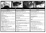
MONTAGGIO MANUBRIO (Fig. 1-2-3)
Sollevare il manubrio come mostra la Fig. 1. Serrare i
pomelli (A, Fig. 3) dopo avere posizionato il manubrio
(B) e deciso l’altezza dello stesso, scegliendo una delle
tre posizioni (C, Fig. 2).
ALTEZZA DEL MANUBRIO (Fig. 3)
Svitare i pomelli (A) ed alzare o abbasare il manubrio
(B).
FASCETTE
Bloccare i cavi sul manubrio con le apposite fascette
(Fig.1A).
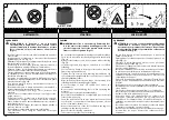
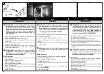
SACCO RACCOGLI ERBA (Fig. 4-5-6)
- Infilare il telaio (A) nel sacco (B) come indicato in
figura 4.
- Fissare i bordi in plastica del sacco (C) sul telaio
aiutandosi con una punta o un cacciavite (Fig. 5).
- Montare la chiusura scarico (D, Fig.6) fissandola con
le 2 viti (E).
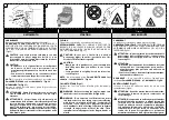
POSIZIONAMENTO DEL SACCO (Fig. 7-8)
- Alzare il deflettore (A).
- Appoggiare i due ganci (B) sul perno del deflettore.
- Abbassare il deflettore e assicurarsi che chiuda
completamente la parte superiore del sacco
raccoglierba.
ASSEMBLAGE DU GUIDON (Fig. 1-2-3)
Soulever le guidon comme indiqué par la Fig. 1. Serrer
les pommeaux (A, Fig. 3) après avoir positionné le
guidon (B) et décidé l’hauteur du même, en
choisissant une des trois positions (C, Fig. 2)
HAUTEUR DU GUIDON (Fig. 3)
Dévisser les pommeaux (A). Lever ou baisser le guidon
(B).
COLLIERS
Retenir les câbles sur le guidon à l'aide des colliers
prévus à cet effet (Fig.1A).
SAC COLLECTEUR D’HERBE (Fig. 4-5-6)
- Enfiler l’armature (A) dans le sac (B): voir schema (Fig.
4).
- Fixer les rebords de plastique du sac (C) sur
l’armature à l’aide d’un tournevis (Fig. 5).
- Monter le dispositif de fermeture de l’éjection (D,
Fig.6) en le fixant avec les 2 vis (E).
MISE EN PLACE DU SAC (Fig. 7-8)
- Lever le déflecteur (A).
- Poser les deux crochets (B) sur le pivot du déflecteur.
- Baisser le déflecteur et s’assurer qu’il obture
hermétiquement l’ouverture supérieure du sac
d’herbe.
FIXING HANDLE (Fig. 1-2-3)
Lift the handle as in Fig. 1. Tighten the knobs (A, Fig. 3)
after positioning the handle (B) at the correct height.
Choose one of the three positions (C, Fig. 2).
HANDLE HEIGHT ADJUSTMENT (Fig. 3)
Unscrew knobs (A) and lift or lower the handle (B).
TIES
Secure the cables to the handle with the supplied ties
(Fig.1A).
GRASS CATCHER (Fig. 4-5-6)
- Insert the frame (A) into the catcher (B) as shown
(Fig. 4).
- Fix the plastic border of the catcher (C) on the frame
by means of a screwdriver (Fig. 5).
- Mount the discharge closing piece (D, Fig.6) securing
it with 2 screws (E).
POSITIONING OF GRASS CATCHER (Fig. 7-8)
- Lift rear deflector (A).
- Attach the two hooks (B) onto the deflector support
shaft.
- Lower rear deflector and make sure it covers
completely the upper part of the grass catcher.
Italiano
Français
English
ASSEMBLAGGIO
ASSEMBLAGE
ASSEMBLY
2
3
4
1
1A


