background image

31

2.  

USE AND TECHNICAL DESCRIPTION

2.1   MACHINE USE

The machine of the AP 105 type with the commercial name FRONTJET is a four-wheel self-propelled mowing machine 
intended for the mowing of maintained grass areas with the maximum height of vegetation of 10 cm, e.g. in parks, gardens and 
playgrounds, contingently on gentle slopes on which there are no foreign objects (fallen branches, stones, solid objects, etc.). 
The gradient of slope must not exceed 14°(25%).
Always slow down when driving on an uneven ground, and use the ramps when crossing a local unevenness higher than 8 cm 
(kerbs). Without use of the ramps there is a danger of a serious damage to the machine.  
Only the accessories whose usage is approved by the machine manufacturer may be connected to the mower. The use of other 
accessory means the immediate loss of the guarantee.
Carry out the mowing connected with mulching regularly every 14 days provided the height of the vegetation does not exceed 
10 cm. The higher vegetation can be a cause of a worse quality of the work. If the vegetation is higher, mow several times 
using mutally overlaping runs. At the fi rst run select the maximum height position setting of the mowing mechanism, and at the 
next run set the height corresponding to the required height of vegetation. The pulped grass matter is evenly thrown all over the 
mowed surface and serves as a green manure and protection of the soil against waste of moisture. This is especially important 
during the summer season. 

To ensure correct function of the machine and high quality mulching, it is necessary to always mow 

only approx. 1/3 of the height of the growth. 

WARNING: Mulching may contribute to the soil acidity.  


2.2   TECHNICAL DESCRIPTION 

The AP 105 self-propelled mowing machine consists of the following basic groups:

2.2.1 MACHINE 

FRAME

The machine frame is welded from steel profi les and metal sheets of 3 mm thickness. It is a supporting element of the engine, gearbox, 
front and rear axles, steering, drives, mowing mechanism, accumulator, fuel tank and other needed equipment of the machine.

2.2.2  ENGINE INCLUDING ELECTRICAL EQUIPMENT

The engines used in mowing machines are four-stroke petrol engines with vertical output shaft. The engine is fastened fi rmly 
to the frame in the machine rear part. The drive from the engine is transmitted to the gearbox by a V-belt. The accumulator is 
positioned under the engine bonnet on the right-hand side of the seat. 

2.2.3  GEARBOX INCLUDING DRIVE OF FRONT WHEELS

The gearbox is of a type with a hydrostatic transmission of power. The gear change is carried out by depressing the travel pedal 
smoothly forwards or backwards.

2.2.4  REAR AXLE WITH WHEELS INCLUDING STEERING UNIT

The rear axle is of a massive cast-iron construction. It is suspended on a hollow pivot enabling the swing of the wheels. The 
steering is performed from the steering whel shaft via a link chain ended on both sides with stranded wires and tensioning screws.  

2.2.5 BY-PASS

The by-pass lever serves for the disengaging and engaging of the drive from the gearbox to the front wheels. It is located 
behind the front left wheel in the space of the frame.  

2.2.6  BONNET AND PLACE OF OPERATOR 

The bonnet is made of plastics. The metal parts coherent with bonnet are protected with powder painting. The place of the 
operator is solved ergonomically so that all control elements are easily accessible and lightly controllable. The seat used 
ensures the comfortable operating.

2.2.7 MOWING 

MECHANISM

The mowing mechanism is located on the front side of the machine. It consists of a cover, pulleys, shaft with bearings and two 
mowing knives. The drive of the mowing mechanism is carried out by a V-belt from the engine via an electromagnetic clutch 
which is fi xed on the output shaft of the engine.
 

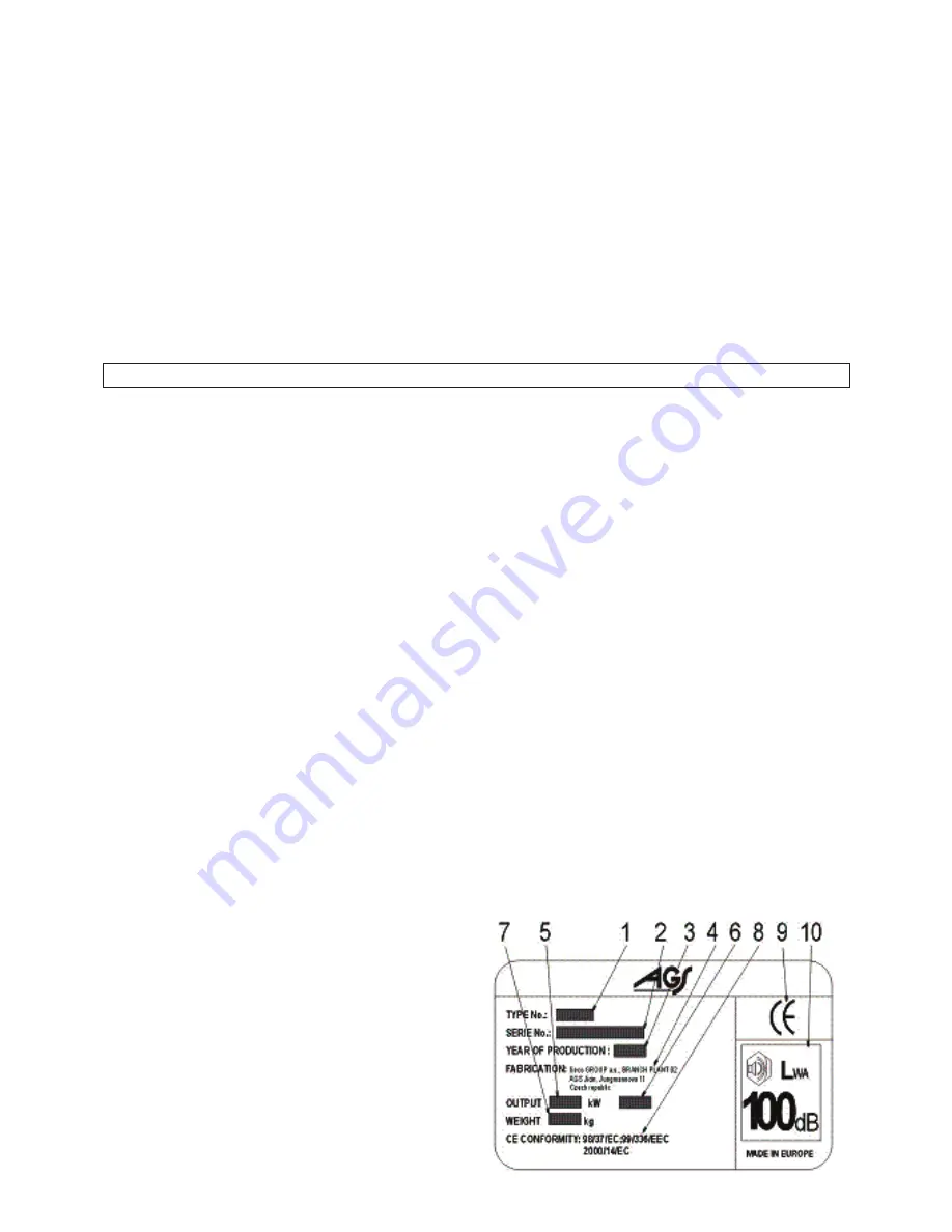
2.3 MARKING

Each self-propelled mowing machine is marked with an identifi cation 
plate located under the seat. It includes the following data:
1.  Type of machine
2. Serial number
3.  Year of production
4.  Name and address of manufacturer
5. Engine power output
6.  Engine speed in rpm
7. Weight
8.  EC regulations the conformity of product was judged with 
9  Mark of product conformity
10. Guaranteed noise level acc. to the 2000/14/EC directive

The serial number will be recorded on the second page of this 
manual cover by the dealer during the machine handing over.

Summary of Contents for TWISTER 106

Page 1: ...NÁVOD K POUŽITÍ OPERATOR S MANUAL BEDIENUNGSANLEITUNG MANUALE DI ISTRUZIONE MODE D EMPLOI HANDBOK INSTRUKCJA OBSŁUGI TWISTER 106 125 FrontCut106 125 EN CZ DE IT FR SV PL ...

Page 2: ...Česky 1 English 25 Deutsch 49 Italiano 73 Français 97 Svenska 121 Polski 145 ...

Page 3: ... 12 6 1 9 Pedál pojezdu 12 6 1 10 Páka by passu 13 6 1 11 Páka nastavení výšky žacího ústrojí 13 6 2 Provoz a obsluha 13 6 2 1 Nastartování motoru 13 6 2 2 Zastavení motoru 13 6 2 3 Zapnutí a vypnutí žacího ústrojí 14 6 2 4 Nastavení výšky žacího ústrojí 14 6 3 Pojezd 14 6 4 Rychlost pojezdu a sečení trávy 14 6 5 Jízda na svahu 14 7 Údržba stroje 15 7 1 Přehled kontroly a údržby 15 7 2 Kontrola tl...

Page 4: ...O 3767 1 3 D Posouzení shody bylo provedeno postupem stanoveným v Směrnice rady č 98 37 EC Článek 8 odstavec 2 a eqv 3 odst 1 a NV č 170 1997 Sb Směrnice rady č 89 336 EEC Článek 10 odstavec 1 eqv 4 odst 1 NV č 169 1997 Sb Směrnice 2000 14 EC Příloha VIII E Potvrzujeme že toto strojní zařízení definované uvedenými údaji je ve shodě s požadavky uvedenými ve výše uvedených technických předpisech a je...

Page 5: ...oveným v Směrnice Rady č 98 37 EC Článek 8 odstavec 2 a eqv 3 odst 1 a NV č 170 1997 Sb Směrnice Rady č 89 336 EEC Článek 10 odstavec 1 eqv 4 odst 1 NV č 169 1997 Sb Směrnice Rady č 2000 14 EC Příloha VIII eqv příloha 7 NV č 9 2002 Sb s dohledem notifikované osoby LRQA registrační číslo 0088 Hiramford Middlemarch Office Village Siskin Drive Coventry CV3 4FJ United Kingdom E Potvrzujeme že toto str...

Page 6: ...akým způsobem budete s tímto strojem pracovat aby Vám co nejdéle sloužil k Vaší spokojenosti Prostudujte si pečlivě tento návod Postupujte přesně podle pokynů v něm uvedených abyste si usnadnili nejen používání zakoupeného stroje ale také zajistili jeho optimální využívání a dlouhou životnost Používejte tento samojízdný žací stroj jen k tomu účelu ke kterému byl zhotoven Jakékoliv použití neuveden...

Page 7: ...otor a vyjměte klíček ze zapalování když čistíte stroj odstraňujete zanesení žacího ústrojí travou jste najeli na cizí předmět a je třeba zjistit nedošlo li k poškození stroje popř poškození odstranit stroj nepřirozeně silně vibruje a je třeba zjistit příčinu vibrací opravujete motor nebo jiné pohyblivé části odpojte i kabely od zapalovacích svíček Než začnete práci se strojem odstraňte z plochy n...

Page 8: ...jámy příkopu nebo hrany která se může utrhnout Nesekejte mokrou trávu snížená přilnavost může být příčinou smyku Nezkoušejte udržet stabilitu stroje šlápnutím na zem 1 1 3 BEZPEČNOST DĚTÍ Pokud obsluha žacího stroje není připravena na přítomnost dětí může se přihodit tragická nehoda Pohyb žacího stroje přitahuje jejich pozornost Nikdy nespoléhejte na to že děti zůstanou tam kde jste je viděli stát...

Page 9: ...potřebného vybavení stroje 2 2 2 MOTOR VČETNĚ ELEKTROINSTALACE Motory používané v žacích strojích jsou čtyřtaktní benzinové motory s vertikální vývodovou hřídelí Motor je pevně připevněn k rámu v zadní části stroje Pohon od motoru k převodové skříni je přenášen klínovým řemenem Akumulátor je umístěn na pravé straně vedle sloupku sedadla pod kapotou motoru 2 2 3 PŘEVODOVÁ SKŘÍŇ VČETNĚ POHONU PŘEDNÍ...

Page 10: ... A1 A2 Souhrnná hodnota zrychlení vibrací přenášených na ruku paži obsluhy ahv min s 2 dle ČSN EN 836 A1 A2 0 94 m s 2 2 5 m s 2 0 7 m s 2 2 5 m s 2 Frontjet AT 125 Motor Briggs Stratton 17 5HP INTEK HONDA 16 HP GCV Objem cm3 502 530 Počet válců 1 2 Otáčky min 1 Palivo Objem nádrže l Rozměry stroje délka x šířka x výška mm Rychlost max vpřed vzad km hod Akumulátor Kola zadní tlak v pneumatikách Ko...

Page 11: ...pravu žacího stroje do provozu Váš prodejce dle pokynů výrobce 4 2 1 MONTÁŽ VOLANTU Umístěte žací stroj na rovnou plochu a srovnejte zadní kola do přímého směru Nasaďte volant a zajistěte jej ve zvolené výškové poloze dodaným kolíkem v odpovídajícím otvoru 4 2 2 MONTÁŽ SEDADLA Sundejte krycí obal sedadla Přiložte sedadlo na jeho místo ve stroji a připevněte jej pomocí šroubů tak jak jsou v sedadle...

Page 12: ...ějte pouze při zastaveném a studeném motoru Používejte jen benzín s oktanovým číslem 95 Natural 95 Nádrž je umístěna ve sloupku sedadla a je snadno přístupná po odklopení sedadla směrem dopředu Uzávěr nádrže otvírejte pomalu protože v nádrži může být přetlak benzínových výparů Při doplňování nádrže používejte kanystr s nálevkou nádrž nepřeplňujte Výšku hladiny benzínu v nádrži lze sledovat pohlede...

Page 13: ...trojí pouze při plně vysunutém elektrickém šroubu 6 1 2 SPÍNACÍ SKŘÍŇKA Klíček má 3 polohy OFF zapalování vypnuto ON zapalování zapnuto START spuštění motoru 6 1 3 PÁČKA PLYNU Reguluje otáčky motoru její jednotlivé polohy jsou obrázek ze 6 1 3 MIN volnoběžné otáčky motoru MAX maximální otáčky motoru SYTIČ start motoru za studena Sytič je na stroji instalován v závislosti na typu motoru 6 1 4 SYTIČ...

Page 14: ...7 BRZDA Když je pedál brzdy plně sešlápnut je žací stroj zabrzděn Nikdy nepoužívejte brzdu současně s funkcí pojezdu hrozí nebezpečí poškození převodovky 6 1 8 PÁKA PARKOVACÍ BRZDY Páka parkovací brzdy má 2 polohy Před nastavením páky do polohy P sešlápněte pedál brzdy Odbrzdění parkovací brzdy se provede sešlápnutím pedálu brzdy při tom se aretace zajištění páky automaticky uvolní ODBRZDĚNO ZABRZ...

Page 15: ... 9 Páčku plynu 6 1 3 nastavte do polohy MAX Vytáhněte sytič 6 1 4 Nemanipulujte s pákou nastavení výšky žacího ústrojí 6 1 11 Otočte klíčkem zapalování 6 1 2 do polohy START Doba startování nesmí překročit 10 sekund hrozí poškození bateriového spínače Motor běží pusťte klíček zapalování Klíček se automaticky vrátí do polohy ON Postupně zasuňte sytič 6 1 4 Páčku ovládání plynu 6 1 3 pomalu nastavte...

Page 16: ...N Při rozjíždění pomalu sešlapujte pedál pojezdu 6 1 9 dle požadovaného směru jízdy při rychlém sešlápnutí pedálu hrozí nebezpečí úrazu Změna směru pojezdu vpřed vzad je možná pouze po zastavení stroje Pokud není stroj zastaven hrozí porucha převodovky Nikdy nepoužívejte pedál pojezdu a pedál brzdy současně jinak hrozí porucha převodovky UPOZORNĚNÍ Zastavení stroje je možné pouze pozvolným uvolněn...

Page 17: ...kud je žací stroj více zatěžován nebo pracuje při venkovních teplotách okolo 35 C nebo vyšších 2 V případě práce stroje v prašném prostředí provádějte kontrolu častěji 3 Kontrolu provádějte častěji pokud stroj pracuje v písčitém prostředí 4 Kontrolu provádějte častěji je li nasazen nový řemen 7 2 KONTROLA TLAKU PNEUMATIK Dodržujte předepsaný tlak v pneumatikách a pravidelně jej kontrolujte Jiné ho...

Page 18: ...ice na žacím ústrojí 3 3 Páku zvedání sečení 4 přesuneme do nejnižší polohy 4 Otočná kolečka 5 zajistíme proti otáčení tak aby zjišťovací kolík 6 zapadl do výřezu v držáku koleček 7 5 Pomocí spínače pro ovládání elektrošroubu 9 nastavíme elektrošroub 9 do maximální polohy Odjistíme čep 8 vyjmutím závlačky a elektrošroub 9 pootočíme do svislé polohy tak aby plochou seděl na držáku s dorazovým šroub...

Page 19: ...u 7 5 5 ÚDRŽBA ZAPALOVACÍ SVÍČKY Údržbu provádějte podle pokynů uvedených v Návodu k obsluze motoru 7 6 MAZÁNÍ Mazání provádějte dle mazacího plánu kontrolu funkcí včetně údržby dle přehledu v kap 7 1 Ložiska napínacích kladek vodících kladek a ložiska žacího ústrojí jsou samomazná Před odstavením stroje na delší dobu promažte důkladně všechna místa která mazání vyžadují plastické mazivo olej SAE ...

Page 20: ...iz obrázek výše Při montáži dbejte na to aby vyhnutí lopatek směřovalo nahoru dovnitř pláště žacího ústrojí Nezaměňte levý nůž za pravý U pravého nože je šroub s levým závitem Kontrolujte stav střižných kolíků které slouží jako ochrana žacího ústrojí proti poškození Jsou li střižné kolíky poškozené ihned je vyměňte Připevňovací šrouby nožů dotáhněte pečlivě předepsaným utahovacím momentem 30 3 Nm ...

Page 21: ...v rameni 4 napínací kladky 7 13 VYJMUTÍ ŽACÍHO ÚSTROJÍ ZE STROJE Spusťte žací ústrojí do pracovní polohy přepnutím spínače 6 1 6 Po dosažení polohy spínač uvolněte Zatažením za páku napínací řemenice 4 obr 7 12 uvolněte klínový řemen a sejměte jej s řemenice žacího ústrojí Vyvlékněte pružinu 3 obr 7 12 z ramene napínací kladky Vyvlékněte pružné závlačky z předních čepů 2 a z obou zadních čepů 1 za...

Page 22: ...asazením kola očistěte všechny části a styčné části namažte lehce plastickým mazivem 7 17 ÚDRŽBA HYDROSTATICKÉ PŘEVODOVKY Pro spolehlivou funkci převodovek je nutné udržovat hladinu oleje ve správné výši Předepsané hodnoty jsou uvedeny v tabulce níže Plnící otvor 1 je dole v blízkosti sedadla viz obrázek Při problémech s převodovkou vyhledejte okamžitě pomoc autorizovaného servisu hrozí nebezpečí ...

Page 23: ... chodu stroje vyskočí z řemenice Pokud vyskočí i po přezkoušení dle následujících kroků je třeba řemen vyměnit Zkontrolujte napnutí řemenu dle kap 7 12 V případě potřeby proveďte seřízení napínání Zkontrolujte vedení řemenu Zkontrolujte nastavení výšky sečení v případě potřeby ji seříďte Zjistěte nebrání li pohybu řemenu cizí těleso Jestli ano těleso odstraňte Překontrolujte všechny řemenice Vyhnu...

Page 24: ...dem k odstřiženým či poničeným drážkám Dle potřeby vyměnit Při pojezdu vznikají extrémní kmity Zkontrolujte nejsou li poškozené nebo zdeformované řemenice Dle potřeby proveďte jejich výměnu Zkontrolujte nemá li řemen pojezdu spálená místa či jiné nepravidelnosti Dle potřeby jej vyměňte Zkontrolujte napnutí řemenu pojezdu dle kap 7 11 V případě potřeby proveďte seřízení jeho napnutí Zkontrolujte vy...

Page 25: ...látor může zamrznout a prasknout Dle potřeby uložte akumulátor v chladném a suchém prostředí Nabíjení akumulátoru provádějte každých 30 dní a provádějte pravidelně kontrolu jeho napětí Skladujte žací stroj přikrytý v čistém a suchém prostředí Nejlepší způsob jak zajistit maximální provozuschopnost žacího stroje pro příští sezónu je jeho každoroční prohlídka a seřízení autorizovaným servisem 10 LIK...

Page 26: ...vyráběných strojů proto může dojít k odchylkám textu a vyobrazení této příručky od skutečnosti Z toho nemohou být vyvozovány žádné nároky Tisk rozmnožování zveřejňování a překlad i částí není bez písemného souhlasu Seco GROUP a s povolen Změny jsou vyhrazeny zst18586 ...

Page 27: ...dal 36 6 1 10 By pass lever 37 6 1 11 Mowing mechanism height setting up lever 37 6 2 Operation and attendance 37 6 2 1 Engine starting 37 6 2 2 Engine stopping 37 6 2 3 Mowing mechanism turning on and off 38 6 2 4 Mowing mechanism height setting up 38 6 3 Travel 38 6 4 Travel speed and mowing of grass 38 6 5 Travel on a slope 38 7 Machine maintenance 39 7 1 Summary of checks and maintenance 39 7 ...

Page 28: ...767 1 3 D Judgment of conformity was carried out by means of the procedure set down in Council Directive No 98 37 EC Article 8 par 2 a eqv 3 par 1 a NV no 24 2003 Sb Council Directive No 89 336 EEC Article 10 par c 1 eqv 4 par 1 NV no 18 2003 Sb Directive 2000 14 EC Appendix VIII E We confirm that machine defined by the data stated is in conformity with the requirements specified in technical regulat...

Page 29: ...d by Council Directive No 98 37 EC Article 8 paragraph 2 a eqv 3 paragraph 1 a GO No 170 1997 Coll Council Directive No 89 336 EEC Article 10 paragraph 1 eqv 4 paragraph 1 GO No 169 1997 Coll Council Directive No 2000 14 EC Appendix VIII eqv appendix 7 GO No 9 2002 Coll under the supervision of notified persons LRQA registration No 0088 Hiramford Middlemarch Office Village Siskin Drive Coventry CV...

Page 30: ...led our task It now depends only on You what way of working with this machine You will choose to serve You to Your satisfaction as long as possible Study this manual carefully Follow the instructions stated in it meticulously in order to make the use of the machine bought easy and to ensure its optimum utilization and long service life Use this self propelled mowing machine only for the purpose it...

Page 31: ... and withdraw the key from the ignition if You are cleaning the machine You are removing the clogging of the mowing mechanism with grass You have run on a foreign object and it is necessary to find out if the machine is not damaged contingently to remove the damage machine is unnaturally vigorously vibrating and it is necessary to find out the cause of vibrations You are repairing the engine or othe...

Page 32: ...el gets over the margin of the hollow ditch or edge which can tear off Do not mow wet grass as the reduced adhesion may by a cause of a skidding Do not try to keep stability by stepping on the ground 1 1 3 SAFETY OF CHILDREN A tragic accident can happen if the mowing machine operator is not prepared for the presence of children The movement of the mowing machine attracts their attention Never rela...

Page 33: ...2 2 2 ENGINE INCLUDING ELECTRICAL EQUIPMENT The engines used in mowing machines are four stroke petrol engines with vertical output shaft The engine is fastened firmly to the frame in the machine rear part The drive from the engine is transmitted to the gearbox by a V belt The accumulator is positioned under the engine bonnet on the right hand side of the seat 2 2 3 GEARBOX INCLUDING DRIVE OF FRONT...

Page 34: ...value of vibrations acceleration transferred to operator s arm ahv min s 2 acc to ČSN EN 836 A1 A2 0 94 2 5 0 7 m s 2 2 5 m s 2 Frontjet AT 125 Motor Briggs Stratton 17 5HP INTEK HONDA 16 HP GCV Capacity cm3 502 530 Number of cylinders 1 2 Rotations min 1 Fuel Tank volume l Machine dimensions length x width x height mm Max speed forward backward km hr Accumulator Rear wheels tyre pressure Front wh...

Page 35: ... machine preparation into operation is carried out by Your vendor in accordance with the instructions of the machine manufacturer 4 2 1 ASSEMBLY OF STEERING WHEEL Place the machine on an even surface and align the front wheels into straight direction Mount the steering wheel and lock it in the corresponding hole of the chosen position of height by the pin supplied 4 2 2 ASSEMBLY OF SEAT Remove the...

Page 36: ...thout fuel for safety reasons Fill the tank only if the engine is turned off and is cold Use only the unleaded petrol with octane number 95 Natural 95 The tank is placed in the column of the seat and is easily accessible after tilting the seat forwards Open the tank cap slowly as there may be an overpressure of petrol vapours in the tank When refuelling use a canister with a funnel Do not overfill ...

Page 37: ... the start of the lawn mower only upon full release of the electric screw 6 1 2 SWITCH BOX The key has 3 positions OFF ignition switched off ON ignition switched on START engine starting 6 1 3 GAS CONTROL LEVER It controls the engine revolutions The individual positions of the lever are as follows MIN Engine idle running MAX Engine max revolutions CHOKE Engine cold start The choke is installed in ...

Page 38: ...reatening 6 1 8 PARKING BRAKE LEVER The parking brake lever has 2 positions Before shifting the lever into the P position step on the brake pedal The disengaging of the parking brake is executed by stepping on the brake pedal at this the arrestment of the lever is automatically released Brake released Brake engaged 6 1 9 TRAVEL PEDAL It controls the drive of wheels and machine travel speed in both...

Page 39: ...ontrol lever 6 1 3 to the MAX position Pull out the choke 6 1 4 Do not manipulate the mowing mechanism height setting up lever 6 1 11 Turn the ignition key 6 1 2 to the START position The time of starting must not exceed 10 seconds if this time is exceeded a damage to the battery threatens The engine is running let loose the ignition key The key will automatically return to the ON position Shift i...

Page 40: ...ving off step on the travel pedal 6 1 9 slowly in accordance with the desired direction of the drive at the fast stepping on the pedal there is a danger of injury The change of the drive direction from forward to backward or vice versa is only possible after the machine is stopped If the machine is not stopped there is a danger of the gearbox failure Never use the travel pedal and brake pedal simu...

Page 41: ...s about 35 C or higher 2 Carry out the checking more frequently if the machine works in a dusty environment 3 Carry out the checking more frequently if the machine works in a sandy environment 4 Carry out the checking more frequently if a new belt is put on 7 2 TYRE PRESSURE CHECK Maintain the specified pressures in the tyres and check them regularly Different values of pressure can make the travel...

Page 42: ...e rotating wheels 5 against rotation so that the security pin 6 falls into the opening in the holder of the wheels 7 5 With the help of the switch for controlling the electro screw 9 set the electro screw 9 in the maximum position Un secure the pin 8 by removing the safety pin and turn the electro screw 9 into the vertical position so that the surface sits on the holder with the stop screw 10 whic...

Page 43: ...nstructions 7 5 5 SPARKING PLUG MAINTENANCE Carry out the maintenance according to the instructions included in the engine operating instructions 7 6 LUBRICATION Carry out the lubrication according to the lubrication chart the checks of functions including the maintenance according to the summary in the chapter 7 1 Bearings of tightening rollers guiding rollers and bearings of mowing mechanism are...

Page 44: ...e with the right one The right knife is provided with the screw having left hand thread Check the condition of the shear pins which serve as the protection of mowing mechanism against a damage If the shear pins are damaged replace them immediately Tighten the fixing screws of knives thoroughly with the specified tightening torque of 30 3 Nm The screw is tightened correctly once the tangential spring...

Page 45: ...e arm 4 of the tensioning pulley 7 13 MOWING MECHANISM WITHDRAWAL FROM MACHINE Lower the mowing mechanism to the working position by depressing the switch 6 1 6 Once the position of the switch is attained release it By pulling the lever of the tension pulley 4 pic 7 12 the v belt is released and can be removed from the tension pulley of the cutter mechanism Take out the spring 3 fig 7 12 from the a...

Page 46: ...re than at its dismantling Before putting the wheel on clean all parts and lubricate the contact surfaces slightly with grease 7 17 HYDROSTATIC GEARBOX MAINTENANCE To ensure the reliable function of the gearbox it is necessary to keep the oil level in the correct height The prescribed values are stated in the table below The filling hole 1 is in the vicinity of the seat see the figure If problems wi...

Page 47: ... pulley during machine running If it jumps out even after the check according to the following steps it has to be replaced Check the tension of drive belt according to the chapter 7 12 If need be carry out the adjustment of tensioning Check the belt guiding Check the setting up of the height of mowing if need be adjust it Find out if a foreign object is not obstructing the running of the belt If i...

Page 48: ...d grooves If need be replace them Extreme vibration occurs at driving Check the pulleys if they are not damaged or distorted If need be replace them Check the belt for burned spots or other irregularities If need be replace the belt Check the tension of travel drive belt according to the chapter 7 11 If need be carry out the adjustment of its tensioning Check the balance of the mowing knives If ne...

Page 49: ...arged accumulator may freeze and burst Store the accumulator if need be in a cold and dry place Charge the accumulator every 30 days and check its voltage regularly Store the mowing machine covered in a clean and dry place The best way how to ensure the maximum serviceability of the mowing machine for the next season is an annual check and adjustment by the authorized service 10 MACHINE DISPOSAL T...

Page 50: ...nes being manufactured therefore the text and illustrations in this manual may vary from the reality No claims may be deduced of that Printing reproduction publishing and translation even partial one is prohibited without consent in writing by the Seco GROUP a s The changes are reserved ...

Page 51: ...PASSU 61 6 1 11 Hebel zum Einstellen der Arbeitshöhe 61 6 2 Betrieb und Bedienung 61 6 2 1 Anlassen des Motors 61 6 2 2 Abstellen des Motors 61 6 2 3 Ein und Abschalten des Mähwerkes 62 6 2 4 Einstellung der Arbeitshöhe des Mähwerkes 62 6 3 Fahren 62 6 4 Geschwindigkeit der Fahrt und das Rasenmähen 62 6 5 Fahren am Hang 62 7 Instandhaltung 63 7 1 Übersicht über die Kontrollen und Instandhaltungen ...

Page 52: ... 201 ČSN EN ISO 3767 1 3 D Die Gleichheit wurde nach folgenden Richtlinien festgestellt Richtlinie 98 37 EC Seite 8 Absatz 2 a 3 Absatz 1 a NV č 170 1997 Sb Richtlinie 89 336 EEC Seite 10 Absatz 1 4 Absatz 1 NV č 169 1997 Sb Richtlinie 2000 14 ES Beilage VIII E Wir bestätigen dass dieses Gerät mit den oben definierten Angaben über Gleichheit und den oben angegebenen technischen Angaben im herkömmli...

Page 53: ...rde nach Richtlinie 98 37 EC Teil 8 Absatz 2 a äqu 3 Abs 1 a NV č 170 1997 Sb Richtlinie 89 336 EEC Teil 10 Absatz 1 äqu 4 Abs 1 NV č 169 1997 Sb Richtlinie 2000 14 EC Anlage VIII äqu Anlage 7 9 2002 Sb unter Aufsicht eines Notars der LRQA Registrierung 0088 Hiramford Middlemarch Office Village Siskin Drive Coventry CV3 4FJ United Kingdom E Wir bestätigen das dieses Gerät mit den oben definierten ...

Page 54: ...an Ihnen mit diesem Gerät so zu arbeiten das es lange zu Ihrer Zufriedenheit dient Lesen Sie sorgfältig diese Anweisung Gehen Sie genau nach diesen Anweisungen vor damit sowohl die Benutzung erleichtert wird als auch eine optimale Ausnutzung und lange Lebensdauer Benutzen Sie diesen Rasenmäher nur zu dem Zweck zu dem er hergestellt wurde Jede Benutzung ausserhalb dieses Bereiches kann zu einer Bes...

Page 55: ...r in der Transportposition befinden Schalten Sie immer das Mähwerk und den Motor aus und ziehen Sie den Zündschlüssel ab wenn Sie das Gerät säubern Sie das Mähwerk säubern das Mähwerk beschädigt wurde und Sie feststellen wollen welcher Art die Beschädigung ist es starke Vibrationen gibt und die Ursache festgestellt werden soll der Motor oder andere bewegliche Teile repariert werden ziehen Sie dazu ...

Page 56: ...Mähen Sie keinen nassen Rasen es kann zu Schleudereffekten kommen Versuchen sie nicht die Stabilität des Traktors zu vergrössern indem Sie das Bein auf die Erde geben 1 1 3 SICHERHEIT VON KINDERN Wenn die Bedienung des Traktor nicht auf die Anwesenheit von Kindern vorbereitet ist können sich tragische Unfälle ereignen Die Bewegung des Mähwerks erweckt Ihre Aufmerksamkeit Verlassen Sie sich niemals...

Page 57: ...iche Ausstattung 2 2 2 MOTOR UND ELEKTRIK Es handelt sich um Viertaktmotoren mit vertikaler Antriebswelle Der Motor ist am hinteren Teil des Rasentraktors befestigt Der Motorantrieb wird durch einen Keilriemen zum Getriebe übertragen Die Batterie befindet sich an der rechten Sitzsäule unter der Motorhaube 2 2 3 GETRIEBE UND VORDERRADANTRIEB Das Getriebe ist in mit einer hydrostatischen Leistungsübe...

Page 58: ...N EN 836 A1 A2 GesamtwertderBeschleunigungderübertragenenVibrationen av an die Hand des Bedieners ahv min s 2 nach ČSN EN 836 A1 A2 0 94 2 5 0 7 m s 2 2 5 m s 2 Frontjet AT 125 Motor Briggs Stratton 17 5HP Intek HONDA 16 HP GCV Hubraum cm3 502 530 Zylinder 1 2 Umdrehungen min 1 Treibstoff Tankinhalt l Ausmaße Länge x Breite x Höhe mm Geschwindigkeit max vorwärts rückwärts km h Batterie Räder hinte...

Page 59: ...dieser Arbeit wird diese Tätigkeit durch Ihren Verkäufer durchgeführt nach Angaben des Herstellers 4 2 1 MONTAGE DES LENKRADES Stellen Sie den Rasentraktor auf eine ebene Fläche und stellen Sie dieVorderräder gerade Setzen Sie das Lenkrad in der gewünschten Höhe auf die Lenksäule und sichern Sie es mit dem mitgelieferten Splint 4 2 2 MONTAGE DES SITZES Nehmen Sie die Verpackungshülle des Sitzes ab...

Page 60: ...Treibstoff transportiert wurden Das Einfüllen von Treibstoff nur im geparktem und kaltem Zustand Benutzen Sie nur bleifreies Benzín Natural 95 Der Tank befindet sich unter dem Sitz und ist leicht durch das Klappen des Sitzes nach vorn erreichbar Den Tankdeckel langsam öffnen da sich Überdruck aufgebaut haben kann Zum Einfüllen benutzen Sie einen Kanister und vermeiden Sie den Tank zu überfüllen Die...

Page 61: ...ogener Stellung anlassen 6 1 2 ZÜNDSCHLOSS Der Schlüssel hat drei verschiedene Positionen OFF Zündung aus ON Zündung ein START Anlassen des Motors 6 1 3 GASPEDAL Reguliert die Motordrehzahl in den verschiedenen Positionen Bild 6 1 3 MIN Leerlauf des Motors MAX Maximale Umdrehung des Motors KALTSTARTANLAGE Kaltstart des Motors Der Kaltstarter ist in Abhängigkeit mit dem Motortyp installiert 6 1 4 K...

Page 62: ...NDBREMSHEBEL Die Handbremse hat 2 Stellungen Vor dem Stellen des Hebels in die Position P treten Sie das Bremspedal Durch das erneute Treten des Bremspedals wird die Handbremse erneut gelöst UNGEBREMST GEBREMST 6 1 9 FAHRPEDAL Bestimmt den Antrieb der Hinterräder und reguliert die Geschwindigkeit in beide Richtungen Antrieb vorwärts Treten Sie langsam das Fahrpedal in Richtung F mit einem weiteren...

Page 63: ...4 Manipulieren Sie nicht mit dem Mähwerkhebel 6 1 11 Drehen Sie den Schlüssel in die Position 6 1 2 START Die Zeit des Anlassens darf 10 Sekunden nicht überschreiten ansonsten droht die Beschädigung des Batterieschalters Sobald der Motor läuft lassen Sie den Zündschlüssel los Der Schlüssel kehrt automatisch in die Lage ON zurück Nehmen Sie den Kaltstarter langsam zurück 6 1 4 Den Gashebel langsam ...

Page 64: ...langsam das Fahrpedal in die gewünschte Richtung treten 6 1 9 bei einem schnellen Durchtreten kann es zu Unfällen kommen Ein Richtungswechsel vorwärts rückwärts ist nur nach demAnhalten des Gerätes möglich Wenn das Gerät nicht steht kann es zu einem Getriebeschaden kommen Benutzen Sie niemals Fahrpedal und Bremspedal gleichzeitig es kann zu Getriebeschäden kommen ACHTUNG Ein Anhalten ist nur durch...

Page 65: ... wird und oder die Arbeiten um 35 C oder höher erfolgen 2 Wenn des Gerät in staubigen Bereichen arbeitet machen Sie die Kontrollen öfters 3 Die Kontrolle ist öfters durchzuführen wenn in einem sandigen Bereich gearbeitet wird 4 Die Kontrolle ist öfters durchzuführen wenn die Keilriemen neu sind 7 2 KONTROLLE DES LUFTDRUCKS Halten Sie den vorgeschriebenen Reifendruck ein und kontrollieren Sie Ihn r...

Page 66: ...n 4 4 Die Drehrädchen 5 werden so gegen Drehen gesichert das der Sicherungsbolzen 6 in den Ausschnitt neben dem Halter fällt 7 5 Mit Hilfe des Schalters für die Elektroschraube 9 stellen wir diese 9 in die max Höhe Wir entsichern den Bolzen 8 durch Herausnehmen des Sperrstiftes und die Eletroschraube 9 drehen wir in die waagerechte Lage so das diese flächig auf dem Hebel mit Halteschraube10 welche ...

Page 67: ...ng zum Motor durch 7 5 5 INSTANDHALTUNG DER ZÜNDKERZEN Die Wartung der Zündkerzen führen Sie nach den Anweisungen in der Betriebsanweisung zum Motor durch 7 6 SCHMIERUNG Die Schmierung führen Sie nach dem Schmierplan durch Kontrolle der Funktion incl Wartung nach der Übersicht in Kapitel 7 1 Die Lager der Spannrollen der Führungs rollen und die Lager des Mähwerkes sind selbstschmierend Vor der Ein...

Page 68: ...er Montage achten Sie darauf dass die Ausbuchtung der Messer nach oben in das Mähwerk zeigen Vertauschen Sie nicht das linke Messer mit dem rechten Am rechten Messer hat die Schraube ein Linksgewinde Kontrollieren Sie die Haltebolzen welche als Schutz des Mähwerkes gegen Beschädigung dienen Sind diese Bolzen beschädigt wechseln Sie sie sofort aus DieBefestigungsschraubenziehenSiesorgfältigmitdemvo...

Page 69: ...tsposition 6 1 6 Nach dem Erreichen der Stellung den Schalter loslassen Mit demAnziehen des Hebels des Riementriebs 4 Bild 7 12 wird der Keilriemen gelöst und kann vom Riementrieb des Mähwerkes genommen werden Durch Verschieben des Hebels der Riemenspannung 4 Bild 7 12 lösen Sie den Keilriemen und nehmen Sie ihn heraus Nehmen Sie die Spannfeder 3 Bild 7 12 aus dem Rahmen der Spannrolle Nehmen Sie ...

Page 70: ...te Reihenfolge zu benutzen Vor dem Anschrauben säubern Sie die Räder und schmieren Sie die Auflageflächen leicht mit einem plastischen Schmiermittel 7 17 WARTUNG DES GETRIEBES Für eine verlässliche Funktion des Getriebes ist es notwendig den Ölstand des Getriebeöls in der richtigen Höhe zu halten Die vorgeschriebenen Werte sind in der Tabelle unten aufgeführt Die Füllöffnung befindet sich in Sitznähe...

Page 71: ...olgenden Schritte wieder abspringt ist er zu wechseln Kontrollieren Sie die Riemenspannung nach Kapitel 7 12 Gegebenenfalls stellen Sie ihn ein Kontrollieren Sie die Riemenführung Kontrollieren Sie die Einstellung der Mähhöhe gegebenenfalls einstellen Stellen Sie fest ob sich nicht ein fremder Gegenstand im Riementrieb befindet Wenn ja entfernen Sie ihn Kontrollieren Sie alle Riemen Ausgebeulte ode...

Page 72: ...getrennte oder unbrauchbare Führungen Nach Bedarf wechseln Bei der Fahrt kommt es zu extremen Schwingungen Kontrollieren Sie ob die Riemenantriebe nicht deformiert oder beschädigt sind Nach Bedarf wechseln Kontrollieren Sie ob die Riemen keine verbrannten Stellen oder andere Unregelmässigkeiten haben Nach Bedarf wechseln Kontrollieren Sie die Spannung des Antriebsriemen nach Kapitel 7 11 Gegebenen...

Page 73: ...Sie destilliertes Wasser auf und laden Sie sie Eine ungeladene Batterie kann einfrieren und zerplatzen Nach Benutzung lagern Sie die Batterie in einem kühlen und trockenen Raum Das Aufladen der Batterie sollte alle 30 Tage erfolgen und die Spannung ist regelmässig zu kontrollieren Lagern Sie das Gerät in einem trockenen und sauberen Raum ein Die beste Möglichkeit Ihr gerät auf die nächste Saison vo...

Page 74: ...Weiterentwicklungen vor Aus diesem Grund können keine Ansprüche geltend gemacht werden Druck Vervielfältigung Veröffentlichung und Übersetzung auch Teile sind ohne schriftliche Genehmigung der Seco GROUP a s nicht erlaubt Änderung sind vorbehalten ...

Page 75: ...i taglio in altezza 85 6 2 Funzionamento e comando 85 6 2 1 Avviamento motore 85 6 2 2 Arresto motore 85 6 2 3 Inserimento e disinserimento dell apparato di taglio 86 6 2 4 Regolazione dell apparato di taglio in altezza 86 6 3 Avanzamento 86 6 4 Velocità di avanzamento e il taglio dell erba 86 6 5 Marcia sul pendio 86 7 Manutenzione della macchina 87 7 1 Tabella riassuntiva dei controlli e della m...

Page 76: ...7 1 3 D La valutazione della conformitŕ č stata eseguita con le procedure stabilite in Direttiva del Consiglio n 98 37 EC Articolo 8 comma 2 a eqv 3 comma 1 a NV n 170 del 1997 Direttiva del Consiglio n 89 336 EC Articolo 10 comma 1 a eqv 4 comma 1 a NV n 169 del 1997 Direttiva 2000 14 EC Allegato VIII E Confermiamo che questo dispositivo macchinario definito con i dati sopraindicati conformemente ...

Page 77: ...rmità è stata eseguita in accordo con le procedure definite da Direttiva di Consiglio N 98 37 EC Articolo 8 paragrafo 2a eqv 3 paragrafo 1 a GO N 170 1997 Coll Direttiva di Consiglio N 89 336 EEC Articolo 10 paragrafo 1 eqv 4 paragrafo 1 GO N 169 1997 Coll Direttiva di Consiglio N 2000 14 EC Appendice VIII eqv Appendice 7 GO N 9 2002 Coll sotto la supervisione del notaio LRQA registrazione N 0088 H...

Page 78: ... questa macchina perchč Le possa servire piů lungo a Sua piena soddisfazione La preghiamo di studiare bene il presente manuale di istruzioni La preghiamo di procedere precisamente secondo le istruzioni riportate per rendere piů facile l uso della macchina acquistata ma anche per assicurare il suo ottimo utilizzo e la lunga durata di sua vita La preghiamo di usare questa falciatrice semovente solo ...

Page 79: ... apparato di taglio il motore e togliere la chiave dall avviamento sempre quando si pulisce la macchina si elimina l erba che ha intasato l apparato di taglio si č urtato contro un oggetto estraneo occorre ricercare l eventuale danneggiamento della macchina e ripararla la macchina vibra eccezionalmente occorre ricercare il motivo delle vibrazioni si ripara il motore o altre parti movibili scollega...

Page 80: ...ce puň ribaltarsi improvvisamente se una ruota č fuori dal bordo di una fossa o bordo che puň staccarsi Non falciare l erba umida la bassa aderenza puň diventare la causa di scivolamento Non provare a mantenere la stabilitŕ della macchina appoggiando il piede sulla terra 1 1 3 SICUREZZA DEI BAMBINI Gli infortuni possono succedere nel caso quando non si fa attenzione alla presenza di bambini Macchi...

Page 81: ...lle falciatrici sono a benzina a quattro tempi con l albero d uscita verticale Il motore č saldamente fissato al telaio nella parte posteriore della macchina La potenza č trasmessa dal motore alla scatola del cambio con una cinghia trapezoidale L accumulatore che serve all avviamento del motore č ubicato sotto il cofano del motore 2 2 3 SCATOLA DEL CAMBIO DI VELOCITA E TRAZIONE SULLE RUOTE ANTERIOR...

Page 82: ...ione vibrazioni trasmesse alla mano braccio dell operatore ahv min s 2 ai sensi della ČSN EN 836 A1 A2 0 94 2 5 0 7 m s 2 2 5 m s 2 Frontjet AT 125 Motore Briggs Stratton 17 5HP INTEK HONDA 16 HP GCV Capacità cm3 502 530 Cilindri no 1 2 Giri min 1 Carburante Volume del serbatoio l Dimensioni della macchina lunghezzaxampiezzaxaltezza mm Massima velocità avanti indietro km hr Accumulatore Ruote post...

Page 83: ...one verrŕ fatta dal venditore secondo le istruzioni della casa costruttrice 4 2 1 MONTAGGIO DEL VOLANTE Posizionare la falciatrice su una superficie piana ed allineare le ruote posteriori in direzione diretta Inserire il volante e bloccarlo in posizione scelta tramite il perno 2 in dotazione mettendolo nel rispettivo foro 4 2 2 MONTAGGIO DEL SEDILE Togliere l imballo protettivo dal sedile Installar...

Page 84: ...rbatoio sempre solo al motore fermo e freddo Utilizzare solo la benzina con numero di ottani 95 Natural 95 Il serbatoio č ubicato nella colonna del sedile ed č di facile accesso dopo il ribaltamento del sedile in avanti Aprire lentamente il tappo del serbatoio Nel serbatoio si puň creare la sovrapressione dovuta ai vapori di benzina Per il rifornimento di benzina usare il bidone con imbuto non tra...

Page 85: ...e della falciatrice da prato solo dopo allentamento della vite elettrica 6 1 2 BLOCCHETTO DI ACCENSIONE La chiave ha 3 posizioni OFF l accensione disattivata ON l accensione attivata START l avviamento motore 6 1 3 LEVA DELL ACCELERATORE Regola i giri del motore puň assumere le seguenti posizioni figura nel cap 6 1 3 MIN marcia in folle MAX max giri motore DISPOSITIVO D AVVIAMENTO avviamento motore...

Page 86: ...ggiamento del cambio 6 1 8 LEVA DEL FRENO DI STAZIONAMENTO La leva del freno di stazionamento ha 2 posizioni Prima di mettere la leva nella posizione P schiacciare il pedale del freno Il disinnesto del freno di stazionamento avviene schiacciando il pedale del freno il bloccaggio della leva viene automaticamente rilasciato SFRENATO FRENATO 6 1 9 PEDALE DI AVANZAMENTO Comanda la trazione delle ruote...

Page 87: ...SERITO Attenzione non schiacciare il pedale di avanzamento 6 1 9 Spostare la leva dell acceleratore 6 1 3 nella posizione MAX Tirate fuori il dispositivo d avviamento 6 1 4 Non spostare la leva di sollevamento dell apparato di taglio 6 1 11 Ruotare la chiave d accensione 6 1 2 nella posizione START La durata dell avviamento non deve superare 10 secondi c č rischio del danneggiamento dell interrutt...

Page 88: ...ntamente il pedale di avanzamento 6 1 9 n direzione richiesta premendo velocemente il pedale c č rischio di un incidente Se si vuole cambiare la direzione avanti indietro occorre fermare la macchina Se la macchina non č ferma si rischia l eventuale difetto della trasmissione Non usare mai il pedale di avanzamento ed il freno contemporaneamente c č rischio del danneggiamento del cambio AVVERTENZA L...

Page 89: ...ne piů caricata o se lavora nelle temperature esterne attorno ai 35 C o superiori 2 Nel caso in cui la macchina lavora in un ambiente polveroso eseguire il controllo piů frequentemente 3 Eseguire il controllo piů frequentemente se la macchina lavora in un ambiente sabbioso 4 Eseguire il controllo piů frequentemente sempre se montata una nuova cinghia 7 2 CONTROLLO DELLA PRESSIONE NEI PNEUMATICI Ma...

Page 90: ...movimento così che il perno di sicurezza 6 cada nell apertura nel dispositivo di fissaggio delle ruote 7 5 Con l aiuto dell interruttore per controllare la vite elettronica 9 posizionate la vite elettronica 9 nella massima posizione Togliete il perno 8 rimuovendo il perno di sicurezza e girate la vite elettronica 9 nella posizione verticale così che la superficie si trovi stretta con la vite di stop...

Page 91: ...tivo al motore 7 6 LUBRIFICAZIONE Lubrificare tutti i punti di lubrificazione secondo lo schema di lubrificazione e controllare le singole funzioni a secondo il riassunto riportato nel cap 7 1 I cuscinetti delle pulegge tendicinghie pulegge conduttrice e cuscinetti dell apparato di taglio sono autolubrificanti Prima di mettere la macchina fuori servizio per un tempo prolungato lubrificare accuratamente...

Page 92: ...apparato di taglio Non scambiare il coltello sinistro per quello destro Il coltello destro č dotato della vite sinistrorsa Controllare lo stato delle spine di taglio che servono da protezione dell apparato di taglio contro il danneggiamento Se le spine di taglio sono danneggiate sostituirle subito Serrare accuratamente le viti di fissaggio dei coltelli alla coppia prescritta di 30 3 Nm La vite è av...

Page 93: ...ggia di tensionamento 7 13 ESTRAZIONE DELL APPARATO DI TAGLIO DALLA MACCHINA Abbassare l apparato di taglio nella posizione di lavoro spostandol interruttore6 1 6 Unavoltaraggiuntalaposizione dell interruttore allentatelo Tirando la leva della puleggia di tensione 4 pic 7 12 il nastro a V è allentato e può essere rimosso dalla puleggia di tensione del meccanismo di taglio Sfilare la molla 3 fig 7 12...

Page 94: ... Prima di montare la ruota pulire tutte le parti e lubrificare le parti di contatto leggermente con il grasso plastico 7 17 MANUTENZIONE DELLA TRASMISSIONE IDROSTATICA Per il funzionamento affidabile delle trasmissioni occorre mantenere il corretto livello dell olio I valori prescritti sono riportati nella tabella seguente Il foro di riempimento 1 si trova giů vicino al sedile vedi figura In caso dei...

Page 95: ...ella macchina salta dalla puleggia Se salta anche dopo la prova eseguita secondo i passi seguenti la cinghia va sostituita Controllare la tensione della cinghia secondo il cap 7 12 Se necessario eseguire la regolazione Controllare la guida della cinghia Controllare la regolazione dell altezza di taglio se necessario regolarla Verificare se un corpo estraneo non impedisca il movimento della cinghia ...

Page 96: ... supporto delle pulegge della frizione puň risultare deformato Se necessario sostituirla La macchina non si muove al premere del pedale di avanzamento Controllare la tensione della cinghia di avanzamento secondo il cap 7 11 Se necessario eseguire la regolazione della sua tensione Controllare la puleggia del motore e del cambio per le fessure danneggiate o tagliate Se necessario sostituirla Durante...

Page 97: ...so e di manutenzione relativo al motore Lubrificare tutti i punti di lubrificazione secondo lo schema di lubrificazione vedi cap 7 6 Allentare la cinghia trapezoidale del comando dell apparato di taglio capitolo 7 12 Rimuoverel accumulatore pulirlo rabboccarloconl acquadistillatafinoallepartiposteriorideglianellideiforidiriempimento e ricaricarlo L accumulatore non ricaricato puň congelare e rompersi ...

Page 98: ...azioni rispetto alla realtŕ nel testo e nelle illustrazioni riportate nel presente manuale Di tale fatto non puň risultare nessun diritto Stampare copiare pubblicazione e traduzione pure delle parti del testo non č ammesso senza il previo consenso scritto da parte della Seco GROUP a s Il costruttore si riserva il diritto di apportare le modifiche ...

Page 99: ...ier du by passu 108 6 1 11 Levier d ajustement de la hauteur du dispositif de coupe 109 6 2 Service et manipulation 109 6 2 1 Démarrage du moteur 109 6 2 2 Arrêt du moteur 109 6 2 3 Enclenchement et mise hors service du dispositif de coupe 110 6 2 4 Ajustement de la hauteur du dispositif de coupe 110 6 3 Course 110 6 4 Vitesse de course et de coupe de l herbe 110 6 5 Course en pente 110 7 Maintena...

Page 100: ...3767 1 3 D L évaluation de la conformité a étée effectuée par la procédure déterminée dans Directive du Conseil n 98 37 CE article 8 paragraphe 2 a équ 3 par 1 a DL n 170 1997 rec Directive du Conseil n 89 336 CE article 10 paragraphe 1 a équ 4 par 1 DL n 169 1997 rec Directive 2000 14 CE Annexe VIII E Nous confirmons que cette machinerie définie par les données ledites est en accord avec les exigen...

Page 101: ...a procédure déterminée dans Directive du Conseil n 98 37 CE article 8 paragraphe 2 a équ 3 par 1 a NV n 170 1997 rec Directive du Conseil n 89 336 CE article 10 paragraphe 1 équ 4 par 1 NV n 169 1997 rec Directive du Conseil n 2000 14 CE Annexe VIII équiv annexe 7 NV n 9 2002 rec sous le patronage d une personne notifiée LRQA numéro de classification 0088 Hiramford Middlemarch Office Village Siski...

Page 102: ...nant que de vous de quelle manière vous travaillerez avec cette machine pour qu elle serve le plus longtemps possible à votre satisfaction Explorez cette notice attentivement Progressez exactement selon les instructions y indiquées pour non seulement vous faciliter l utilisation de la machine acquérie mais aussi pour vous assurez son utilisation optimale et sa longue durée de vie Utilisez cette fa...

Page 103: ...be du dispositif de coupe vous avez heurté en roulant un objet inconnu et il faut verifier si la machine n a pas étée endommagée éventuellement éliminer les dégâts la machine vibre bizarrement fort et il est nécessaire de repérer la cause des vibrations vous réparez le moteur ou d autres parties mouvantes débranchez aussi les câbles des bougies d allumage Avant de commencer le travail avec la machi...

Page 104: ...e renverser subitement si la roue passe le bord de la fosse du fossé ou d un bord qui peut se détacher Ne coupez pas de l herbe humide l adhérence réduite peut être la cause d un dérapage N essayez pas de maintenir la stabilité de la machine en mettant pied à terre 1 1 3 SECURITE DES ENFANTS Si l opérateur de la faucheuse n est pas préparé à la présence d enfants un accident tragique peut arriver ...

Page 105: ... la machine 2 2 2 MOTEUR Y COMPRIS L INSTALLATION ELECTRIQUE Les moteurs utilisés dans les faucheuses sont des moteurs essence à quatre temps à arbre de sortie vertical Le moteur est fixé solidement au châssis dans la partie arrière da la machine La traction du moteur est retransmise vers la boîte d engrenages par une courroie cunéiforme L accumulateur est situé dans la partie droite près de la col...

Page 106: ...ve d accélération des vibrations retransmises sur la main bras de l opérateur ahv min s 2 selon ČSN EN 836 A1 A2 0 94 m s 2 2 5 m s 2 0 7 m s 2 2 5 m s 2 Frontjet AT 125 Moteur Briggs Stratton 17 5HP INTEK HONDA 16 HP GCV Volume cm3 502 530 Nombre de cylindres 1 2 Régime min 1 Carburant Volume du réservoir l Dimensions de la machine longueur x largeur x hauteur mm Vitesse max en avant en arrière k...

Page 107: ...heuse est effectuée par votre vendeur suivant le instructions du constructeur 4 2 1 MONTAGE DU VOLANT Placez la faucheuse sur une surface plane et redressez les roues arrière en sens direct Ajustez le volant et verrouillez le dans l ouverture correspondante à l hauteur de la position choisie par la goupille fournie 4 2 2 MONTAGE DU SIEGE Enlevez l emballage de protection du siège Apposez le siège ...

Page 108: ... est arrêté et froid Utilisez uniquement de l essence à indice d octane 95 Le réservoir est situé dans la colonne du siège et est facilement accessible en soulevant le siège vers l avant Ouvrez doucement le bouchon du réservoir car les vapeurs d essence peuvent causer une surpression à l intérieur de celui ci Lors du remplissage du carburant utilisez un jerrycan avec un entonnoir ne surchargez pas...

Page 109: ...n marche du dispositif de coupe uniquement avec le vis électrique complètement sorti 6 1 2 BOITE DE CONNEXION La clef de contact a 3 positions OFF allumage arrêté ON allumage allumé START mise en marche du moteur 6 1 3 MANETTE DE GAZ Elle régle le régime du moteur ses différentes positions sont figure de 6 1 3 MIN régime de ralenti du moteur MAX régime maximal du moteur SATURATEUR démarrage du mote...

Page 110: ...oîte de vitesses 6 1 8 LEVIER DU FREIN DE PARCAGE Le levier du frein de parcage a 2 positions Appuyez la pédale de frein avant de positionner le levier en position P Le défreinage s effectuera par appui de la pédale de frein à cette occasion l arrêtage de verrouillage du levier se relâchera automatiquement DEFREINE FREINE 6 1 9 PEDALE DE COURSE Elle commande la traction des roues et régle la vites...

Page 111: ...manette de gaz 6 1 3 en position MAX Tirez le saturateur 6 1 4 Ne manipulez pas avec le levier d ajustage de la hauteur du dispositif de coupe 6 1 11 Tournez la clef de contact dans l allumage 6 1 2 en position START La durée du démarrage ne doit pas dépasser 10 secondes danger d endommagement du contacteur de la batterie Le moteur tourne relâchez la clef de contact La clef de contact revient auto...

Page 112: ... le régime du moteur en déplaçant la manette de gaz 6 1 3 en position MIN Lors du démarrage appuyez doucement la pédale de course 6 1 9 selon la direction de course souhaitée lors d un appui brusque de la pédale il y a danger imminent Le changement de direction de la course en avant en arrière est possible seulement après l arrêt de la machine Si la machine n est pas arrêtée il y a risque de panne...

Page 113: ...a faucheuse est plus chargée ou si elle travaille dans des températures aériennes d environ 35 C ou supérieures 2 Effectuez le contrôle plus souvent si la machine travaille dans un milieu poussiéreux 3 Effectuez le contrôle plus souvent si la machine travaille dans un milieu sableux 4 Effectuez le contrôle plus souvent si une nouvelle courroie est montée 7 2 CONTROLE DE LA PRESSION DES PNEUS Respe...

Page 114: ...agez la courroie aussi de la poulie à courroie sur le dispositif de coupe 3 3 Déplacez le levier de levage de la coupe 4 dans la position infime 4 Assurez les roues pivotantes 5 contre leur rotation de telle manière que le goujon d assurage 6 s enfonce dans l entaille du porte roues 7 5 A l aide de l interrupteur de commande du vis électrique 9 ajustez le vis électrique 9 dans la position maximale ...

Page 115: ...on selon le plan de lubrification lecontrôledesfonctionsycompris la maintenance selon l abrégé au chap 7 1 Les paliers des galets de tension des galets de guidage et les paliers du dispositif de coupe sont autolubrifiants Avant de mettre la machine hors de service pour une période de temps prolongée lubrifiez minutieusement touts les endroits qui nécessitent la lubrification graisse plastique huile SA...

Page 116: ...ors du montage veillez à ce que le plie des pales soit orienté vers le haut et vers l interieur de la chape du dispositif de coupe Ne substituez pas la lame gauche par la lame droite La lame droite a un vis à filetage gauche Contrôlez l état des goupilles de cisaillement qui servent comme protection du dispositif de coupe contre l endommagement Si les goupilles de cisaillement sont endommagées remp...

Page 117: ...l par commutation de l interrupteur 6 1 6 Relâchez l interrupteur après avoir atteint la position En tirant sur le levier de la poulie à courroie d attache 4 fig 7 12 libérez la courroie cunéiforme et retirez la de la poulie à courroie du dispositif de coupe Par tirage du levier de la poulie à courroie d attache 4 fig 7 12 libérez la courroie cunéiforme et retirez la Dégagez le ressort 3 fig 7 12 de ...

Page 118: ... nettoyez toutes les partie et lubrifiez légérement les parties de contact par de la graisse plastique 7 17 MAINTENANCE DE LA BOITE DE VITESSES HYDROSTATIQUE Pour un fonctionnement fiable des boîtes de vitesses il est nécessaire de maintenir le niveau d huile à la bonne hauteur Les valeurs prescrites sont indiquées dans le tableau ci dessous L orifice de remplissage 1 est en bas près du siège voir fig...

Page 119: ... peut être endommagée si elle saute hors de la poulie à courroie pendant la marche de la machine Si elle saute aussi après la révision suivant les pas suivants il faut remplacer la courroie Vérifiez la tension de la courroie suivant le chap 7 12 Effectuez le réglage en cas de besoin Vérifiez la ligne de la courroie Vérifiez l ajustage de la hauteur de coupe ajustez la en cas de besoin Repérez si un c...

Page 120: ...urse Lors des déflexions le support des galets de l embrayage peut être courbé Changer selon le besoin La machine n avance pas lors de l appui de la pédale de course Vérifiez la tension de la courroie de course suivant le chap 7 11 Effectuez le réglage de sa tension en cas de besoin Vérifiez la poulie à courroie du moteur et de l embrayage en vue des gorges coupées ou endommagées Changer selon le bes...

Page 121: ... mode d emploi du moteur Lubrifiez touts les points de lubrification suivant le plan de lubrification chapitre 7 6 Détendez la courroie cunéiforme de la traction du dispositif de coupe chapitre 7 12 Retirez l accumulateur nettoyez le rajoutez de l eau distillée jusqu aux parties inférieures des anneaux des orifices de remplissage et chargez le entièrement Un accumulateur non chargé peut geler et éclat...

Page 122: ...rquoi il peut arriver que ce manuel contienne des différences de texte et d illustration par rapport à la réalité De cela ne peuvent être déduites nulles prétentions L impression l autocopie la publication et la traduction même de parties n est pas autorisée sans l accord écrit de Seco GROUP a s Toutes modifications réservées ...

Page 123: ...2 6 1 10 Kopplingsspak 133 6 1 11 Spak för höjdinställning av klippmekanism 133 6 2 Drift och underhåll 133 6 2 1 Starta motorn 133 6 2 2 Stanna motorn 133 6 2 3 Stänga av och sätta på klippmekanism 134 6 2 4 Höjdinställning klippmekanism 134 6 3 Transportering 134 6 4 Körhastighet och klippning av gräs 134 6 5 Förflyttning i sluttning 134 7 Maskinunderhåll 135 7 1 Sammanfattning av kontroller och...

Page 124: ...O 4254 1 ČSN EN ISO 11 201 ČSN EN ISO 3767 1 3 D Bedömning av överensstämmelse har utförts i enlighet med procedurerna i Rĺdets direktiv nr 98 37 EC Artikel 8 par 2 a eqv 3 par 1 a NV no 24 2003 Sb Rĺdets direktiv nr 89 336 EEC Artikel 10 par c 1 eqv 4 par 1 NV no 18 2003 Sb Direktiv 2000 14 EC Appendix VIII E Vi intygar att maskinen som definieras av angiven information uppfyller de krav som anges...

Page 125: ...ägagångssätt enligt Rådets direktiv nr 98 37 EC Artikel 8 paragraf 2 a eqv 3 paragraf 1 a GO nr 170 1997 Coll Rådets direktiv nr 89 336 EC Artikel 10 paragraf 1 eqv 4 paragraf 1 GO nr 169 1997 Coll Rådets direktiv nr 2000 14 EC Bilaga VIII eqv bilaga GO nr 9 2002 Coll under överseende av anmälda personer LRQA registreringsnr 0088 Hiramford Middlemarch Office Village Siskin Drive Coventry CV3 4FJ U...

Page 126: ...ätt du vill att denna maskin ska arbeta för dig och vara till belĺtenhet sĺ länge som möjligt Läs noga denna bruksanvisning Följ instruktionerna för att fĺ mesta möjliga användning av maskinen och för att se till att maskinen används pĺ rätt sätt och att maskinens livslängd blir sĺ lĺng som möjligt Använd endast denna självgĺende ĺkklippare för det syfte den tillverkades för All annan användning u...

Page 127: ...n ur tändlĺset när du rengör maskinen när du tar bort gräs frĺn klippmekanismen när du har kört pĺ ett främmande föremĺl och du mĺste ta reda pĺ om maskinen är skadad eventuellt ta bort skadan när maskinen vibrerar pĺ ett onaturligt sätt och orsaken till vibrationerna mĺste utredas när du reparerar motorn eller andra rörliga delar koppla även loss ledningarna frĺn tändstiften Innan du pĺbörjar arb...

Page 128: ...E UTFÖRAS Klipp inte nära en tipp nära en hĺlighet eller en vall Ĺklipparen kan plötsligt välta om ett hjul kommer över kanten till en hĺlighet dike eller en kant Använd inte ĺkklipparen pĺ blött gräs dĺ hjulen kan förlora fästet och slira Försök inte hĺlla balansen genom att gĺ ner pĺ marken 1 1 3 BARNSÄKERHET En tragisk olycka kan hända om inte användaren är beredd pĺ barns närvaro Ĺklipparen dr...

Page 129: ...h annan nödvändig utrustning 2 2 2 MOTOR INKLUSIVE ELEKTRISK INSTALLERING Motorerna som används i ĺkklipparen är fyrtakts bensinmotor med vertikal utgĺende axel Motorn är ordentligt fastsatt vid ramen i maskinens bakre del Motordriften överförs till växellĺdan via en kilrem Ackumulatorn finns under motorhuven vid sätets högra sida 2 2 3 VÄXELLĹDA INKLUSIVE FRAMHJULSDRIFT Växellĺdan har hydrostatisk...

Page 130: ...rationsökning överförd till förarens arm ahv min s 2 enligt ČSN EN 836 A1 A2 0 94 m s 2 2 5 m s 2 0 7 m s 2 2 5 m s 2 Frontjet AT 125 Motor Briggs Stratton 17 5HP INTEK HONDA 16 HP GCV Volym cm3 502 530 Antal cylindrar 1 2 Motorvarvtal r min Bränsle Tankens kapacitet l Maskindimensioner längd x bredd x höjd mm Max hastighet framĺt back km h Ackumulator Backhjul däcktryck Framhjul däcktryck Växellĺ...

Page 131: ...R ANVÄNDNING Ĺkklipparen förbereds för användning av säljaren enligt tillverkarens instruktioner eftersom särskild teknisk kunskap fordras 4 2 1 RATTMONTERING Placera maskinen pĺ ett jämnt underlag och ställ framhjulen rakt fram Montera ratten och lĺs fast den i det hĺl som motsvarar önskat höjdläge för det medföljande stiftet 4 2 2 MONTERING AV SÄTE Ta bort emballaget runt sätet Sätt sätet pĺ pla...

Page 132: ... av säkerhetsskäl Fyll endast tanken om motorn är avstängd och avsvalnad Använd endast blyfri bensin med oktannummer 95 Normal 95 Tanken är placerad i sätesryggen och kan lätt kommas ĺt när sätet fällts fram Öppna tanklocket försiktigt eftersom det kan finnas ett övertryck av bensinĺngor i tanken Använd en behĺllare med tratt vid pĺfyllningen Fyll inte upp tanken för mycket Bensinnivĺn i tanken kan...

Page 133: ...av en säkerhetsbrytare som gör att det endast är möjligt att starta gräsklipparen om den eldrivna skruven är helt frisläppt 6 1 2 KOPPLINGSDOSA Nyckeln kan sättas i tre lägen OFF tändningen avstängd ON tändningen pĺ START motorn startas 6 1 3 GASREGLAGE Styr motorvarvtalet De olika lägena pĺ spaken är följande MIN Motorn gĺr pĺ tomgĺng MAX Motorn gĺr pĺ max varvtal CHOKE Motorn kallstartas Choken ...

Page 134: ... körfunktionen växellĺdan kan dĺ skadas 6 1 8 PARKERINGSBROMSSPAK Parkeringsbromsspaken har tvĺ lägen Trampa pĺ bromspedalen innan spaken ställs i läge P Parkeringsbromsen slĺs av genom att man trampar pĺ bromspedalen dĺ släpps spärren automatiskt BROMSEN FRIGJORD BROMSEN LIGGER AN 6 1 9 KÖRPEDAL Styr hjuldriften och maskinens körhastighet i bägge riktningar Framĺt Trampa ner pedalen lĺngsamt samt...

Page 135: ...inte trampar pĺ körpedalen 6 1 9 Ställ gasreglaget 6 1 3 i läge MAX Dra ut choken 6 1 4 Ändra inte pĺ klippmekanismens höjdinställningsspak 6 1 11 Vrid tändningen 6 1 2 till START läget Starttiden fĺr inte överskrida 10 sekunder om denna tid överskrids kan batteriet förstöras När motorn är igĺng kan tändnyckeln släppas Nyckeln ĺker automatiskt tillbaka till läge ON För in choken 6 1 4 etappvis Stä...

Page 136: ...bt finns det risk för skador Ändring av körriktning frĺn framĺt till bakĺt eller tvärtom är endast möjlig efter att maskinen stannats Stannas inte maskinen finns det risk för att växellĺdan skadas Använd aldrig körpedalen och bromspedalen samtidigt dĺ det finns risk för att växellĺdan gĺr sönder dĺ VARNING Maskinen kan endast stannas genom att foten gradvis släpps upp från körpedalen och att du sedan...

Page 137: ...an oftare om ĺkklipparen har en högre belastning än normalt eller om den används vid temperaturer pĺ 35 C eller högre 2 Utför kontrollerna oftare om ĺkklipparen används i en dammig miljö 3 Utför kontrollerna oftare om ĺkklipparen används i en sandig miljö 4 Utför kontrollerna oftare om en ny rem har satts pĺ 7 2 KONTROLLAV DÄCKTRYCK Se till att däcken hĺller specificerat tryck och kontrollera dem r...

Page 138: ...ipparen 4 till det lägsta läget 4 Säkra rotationshjulen 5 mot rotation så att säkerhetsstiftet 6 faller in i öppningen i hjulfästet 7 5 Använd omkopplaren för styrning av elektroskruven 9 och ställ in elektroskruven 9 i maxläget Osäkra stiftet 8 genom att ta bort säkerhetsstiftet och ställa elektroskruven 9 i vertikalt läge så att ytan sitter på fästet med stoppskruven 10 som skjuter ut framför ra...

Page 139: ...Byt luftfiltret enligt anvisningen i instruktionerna för motorn 7 6 SMÖRJNING Utför smörjningen enligt smörjschemat kontroll av funktioner ingĺr i underhĺllet se sammanfattningen i kapitel 7 1 Lager för spännrullar styrrullar och lager för klippmekanismen är självsmörjande Innan maskinen ställs undan för en längre tid är det viktigt att smörja alla ställen som behöver smörjas noga fett SAE 30 olja ...

Page 140: ...ens böjning pekar uppĺt i klippmekanismens hus Blanda inte ihop vänster och höger kniv Den högra kniven har en vänstergängad skruv Kontrollera säkerhetsstiftens tillstĺnd De är till för att skydda klippmekanismen mot skador Om säkerhetsstiften är skadade ska de bytas ut genast Dra ĺt fästskruvarna för knivarna med ĺtdragningsmomentet 30 3 Nm Skruven är åtdragen riktigt när tangentialfjädern under ...

Page 141: ...smen till arbetsläge genom att trycka pĺ omkopplare 6 1 6 Släpp omkopplaren genast när slutläget är nĺtt När väl kontaktens läge är uppnått lossar du den Genom att dra i spaken till spännrullen 4 bild 7 12 lossas kilremmen så att den kan tas bort från spännrullen på klippmekanismen Ta ut fjädern 3 fig 7 12 frĺn spännremskivans arm Dra ut de fjädrande saxpinnarna frĺn framstiften 2 och de bägge baks...

Page 142: ...r alla delar och smörj kontaktytorna med lite fett innan hjulet sätts tillbaka 7 17 UNDERHĹLL HYDROSTATISK VÄXELLĹDA För att växellĺdan ska fungera riktigt är det absolut nödvändigt att oljenivĺn alltidärkorrekt Deangivnavärdenabeskrivsitabellennedan Pĺfyllningshĺlet 1 är beläget nära sätet se figur Om problem skulle uppstĺ med växellĺdan kontakta dĺ genast en auktoriserad verkstad annars finns det ...

Page 143: ...ll enligt följande steg har utförts mĺste den bytas ut Kontrollera drivremmens spänning enligt kapitel 7 12 och Justera spänningen om det behövs Kontrollera remstyrningen Kontrollera höjdinställningen pĺ klippningen justera om det behövs Kontrollera att inget främmande föremĺl hindrar remmens drivning Ta bort föremĺlet om sĺ är fallet Kontrollera alla remskivor Böjda eller spruckna remskivor kan o...

Page 144: ...dan beträffande hack eller skador Byt ut dem om det behövs Extrem vibration uppstĺr vid körning Kontrollera att remskivorna inte är förvridna eller skadade Byt ut dem om det behövs Kontrollera remmen beträffande brännmärken eller andra oregelbundheter Byt ut remmen om det behövs Kontrollera drivremmens spänning enligt kapitel 7 11 Justera spänningen om det behövs Kontrollera knivarnas balans Balan...

Page 145: ...lnadshĺlen och ladda upp den helt En oladdad ackumulator kan frysa och gĺ sönder Om det behövs förvara ackumulatorn pĺ en kall och torr plats Ladda ackumulatorn var 30 e dag och kontrollera spänningen regelbundet Förvara ĺkklipparen pĺ ett rent och torrt ställe täck den Det bästa sättet att säkerställa att ĺkklipparen fungerar pĺ bästa sätt nästa säsong är att lĺta en auktoriserad verkstad utföra ...

Page 146: ... reserverar oss därför mot att text och bilder i denna handbok kan avvika frĺn verkligheten Inga krav kan ställas med avseende pĺ detta Tryckning kopiering publicering eller översättning även delvis är förbjuden utan skriftligt medgivande av Seco GROUP a s Med reservation för ändringar ...

Page 147: ... 10 Dźwignia by pass 157 6 1 11 Dźwignia ustawienia wysokości mechanizmu tnącego 157 6 2 Praca i obsługa 157 6 2 1 Uruchomienie silnika 157 6 2 2 Wyłączenie silnika 157 6 2 3 Włączenie i wyłączenie mechanizmu tnącego 158 6 2 4 Ustawienie wysokości mechanizmu tnącego 158 6 3 Jazda 158 6 4 Prędkość jazdy i koszenia trawy 158 6 5 Jazda na zboczu 158 7 Konserwacja maszyny 159 7 1 Przeglądy i konserwac...

Page 148: ...ia podanego w Dyrektywa Rady nr 98 37 EC Artykuł 8 ustęp 2 a ekw 3 ustęp 1 a RRz nr 170 1997 Dz Dyrektywa Rady nr 89 336 EEC Artykuł 10 ustęp 1 ekw 4 ustęp 1 RRz nr 169 1997 Dz Dyrektywa Rady nr 2000 14 EC Załącznik VIII ekw załącznik 7 RRz nr 9 2002 Dz z nadzorem jednostki autoryzowanej LRQA numer rejestracji 0088 Hiramford Middlemarch Office Village Siskin Drive Coventry CV3 4FJ United Kingdom E ...

Page 149: ...o w Dyrektywa Rady nr 98 37 EC Artykuł 8 ustęp 2 a ekw 3 ustęp 1 a RRz nr 170 1997 Dz Dyrektywa Rady nr 89 336 EEC Artykuł 10 ustęp 1 ekw 4 ustęp 1 RRZ nr 169 1997 Dz Dyrektywa Rady nr 2000 14 EC Załącznik VIII ekw załącznik 7 RRz nr 9 2002 Dz z nadzorem jednostki autoryzowanej LRQA numer 0088 Hiramford Middlemarch Office Village Siskin Drive Coventry CV3 4FJ United Kingdom E Potwierdzamy że opisyw...

Page 150: ...jaki sposób będziecie pracować z tą maszyną tak aby jak najdłużej Państwu służyła Prosimy o uważne zaznajomienie się z niniejszą instrukcją Prosimy o ścisłe dotrzymywanie wskazówek podanych w instrukcji w celu nie tylko łatwiejszej obsługi ale również w celu osiągnięcia optymalnego zastosowania oraz długiej trwałości maszyny Kosiarka samojezdna może byś stosowana wyłącznie zgodnie ze swoim przezna...

Page 151: ... na obcy przedmiot to należy wykonać kontrolę czy maszyna nie była uszkodzona lub uszkodzenie usunąć pojawiły się odczuwalne wibracje i należy stwierdzić przyczynę wibracji naprawiasz silnik lub jego części ruchome odłącz kable od świeczek zapłonowych Przed rozpoczęciem pracy z maszyną należy usunąć z powierzchni przeznaczonej pod koszenie wszelkie kamienie kawałki drewna druty kości leżące gałęzi...

Page 152: ...zeże jamy rowu lub krawędzi która może obsunąć się Nie koś mokrej trawy obniżona przyczepność może być przyczyną poślizgu Nie próbuj utrzymać stabilności stawiając nogę na ziemi 1 1 3 BEZPIECZEŃSTWO DZIECI Jeżeli obsługa nie jest przygotowana na obecność dzieci może przydarzyć się tragiczny wypadek Praca kosiarki przyciąga uwagę dzieci Nigdy nie polegaj na to że dzieci zostaną tam gdzie ich widzia...

Page 153: ...o akumulatora zbiornika i pozostałego potrzebnego wyposażenia maszyny 2 2 2 SILNIK WŁĄCZNIE INSTALACJI ELEKTRYCZNEJ W kosiarkach stosowane są czterosuwowe silniki benzynowe z pionowym wałem mechanizmu odbioru mocy Silnik jest połączony z ramą na stało w tylniej części maszyny Napęd z silnika jest przeniesiony do skrzyni biegów przy pomocy pasa klinowego Akumulator jest umieszczony na prawej stroni...

Page 154: ... ogółem av zgodnie z EN 1032 wibracje przeniesione na ręce ahv zgodnie z EN 1033 0 94 m s 2 2 5 m s 2 0 7 m s 2 2 5 m s 2 Frontjet AT 125 Silnik Briggs Stratton 17 5HP Intek HONDA 16 HP GCV Objętość cm3 502 530 Ilość cylindrów 1 2 Obroty min 1 Paliwo Objętość zbiornika l Wymiary maszyny długość x szerokość x wysokość mm Prędkość maks do przodu cofanie km godz Akumulator Koła tylnie ciśnienie w opo...

Page 155: ...do uruchomienia wykonuje sprzedawca zgodnie ze wskazówkami producenta 4 2 1 MONTAŻ KIEROWNICY Kosiarkę należy postawić na równej powierzchni koła przednie koła tylnie ustawić do jazdy wprost Załóż kierownicę i ustal na żądanej wysokości przy pomocy dostarczonego kołka wsuwając go do odpowiedniego otworu 4 2 2 MONTAŻ SIEDZENIA Zdejmij opakowanie ochronne siedzenia Połóż siedzenie na wyznaczonym mie...

Page 156: ...ączonym i zimnym silnikiem Stosuj wyłącznie benzynę 95 oktanową Natural 95 Zbiornik jest umieszczony w kolumnie siedzenia jest łatwo dostępny po odchyleniu siedzenia do przodu Zakrętkę od zbiornika odkręcaj pomału ponieważ w zbiorniku może panować nadciśnienie par benzyny Do uzupełniania zbiornika stosuj karnister z lejkiem nie przepełniaj zbiornika Poziom paliwa w zbiorniku można skontrolować w w...

Page 157: ...żliwia uruchomienie mechanizmu wyłącznie z całkowicie wysuniętą śrubą elektryczną 6 1 2 SKRZYNKA ŁĄCZNIKOWA Klucz ma 3 pozycje OFF zapłon wyłączony ON zapłon włączony START uruchomienie silnika 6 1 3 DŹWIGNIA GAZU Reguluje obroty silnika jej poszczególne pozycje to MIN obroty silnika luz MAX Maksymalne obroty silnika SYTIČ SSANIE start z zimnym silnikiem Ssanie jest zainstalowane w maszynie w zale...

Page 158: ...ocześnie hamulca i funkcji jazdy ryzyko uszkodzenie przekładni 6 1 8 PEDAŁ HAMULCA POSTOJOWEGO Dźwignia hamulca postojowego ma 2 pozycje Przed przesunięciem dźwigni do pozycji P należy wcisnąć pedał hamulca Zwolnienie hamulca postojowego następuje po wciśnięciu pedału hamulca po czym ustalenie pozycji dźwigni zwolni się automatycznie Brake released Brake engaged 6 1 9 PEDAŁ RUCHU Steruje napęd kół...

Page 159: ...u tnącego 6 1 11 Przekręć kluczyk w stacyjce 6 1 2 do pozycji START Czas startu nie może przekroczyć 10 sekund niebezpieczeństwo uszkodzenia włącznika akumulatora Silnik pracuje zwolnij kluczyk zapłonu Kluczyk automatycznie powróci do pozycji ON W kolejności wsuń ssanie 6 1 4 Dźwignię gazu 6 1 3 pomału ustaw do pozycji MIN obniżone obroty silnika Pozostaw silnik w ruchu bez włączonego mechanizmu t...

Page 160: ...dnie z wymaganym kierunkiem jazdy przy energicznym naciśnięciu pedału występuje ryzyko zranienia Zmiana kierunku jazdy do przodu cofanie jest można wyłącznie po zatrzymaniu maszyny Jeżeli maszyna nie zostanie zatrzymana pojawia się ryzyko uszkodzenia przekładni Nigdy nie używaj jednocześnie pedału gazu i hamulca ryzyko uszkodzenia przekładni OSTRZEŻENIE Zatrzymanie maszyny jest możliwe wyłącznie p...

Page 161: ...turach otoczenia około 35 C lub wyższych 2 Kontrolę należy wykonywać częściej jeżeli maszyna pracuje w środowisku o podwyższonym stopniu zakurzenia 3 Kontrolę należy wykonywać częściej jeżeli maszyna pracuje w środowisku w którym występuje piach 4 Kontrolę należy wykonać częściej po każdej wymianie pasa 7 2 KONTROLA CIŚNIENIA OPON Dotrzymuj przepisową wartość ciśnienia w oponach kontrole wykonuj r...

Page 162: ...3 Dźwignię wysokości koszenia 4 przesuń do najniższej pozycji 4 Kółka obrotowe 5 zablokuj przeciwko obracaniu się tak aby kołek blokujący 6 wszedł do wycięcia w uchwycie kółek 7 5 Przy pomocy włącznika do sterowania śrubą elektryczną 9 ustaw śrubę elektryczną 9 do maksymalnej pozycji Odblokuj czop 8 wyciągając zawleczkę a śrubę elektryczną 9 lekko obróć do pozycji pionowej tak aby powierzchnia dol...

Page 163: ...nać zgodnie ze wskazówkami podanymi w Instrukcji obsługi silnika 7 6 SMAROWANIE Smarowanie należy wykonać zgodnie z planem smarowania kontrolę działania poszczególnych czynności włącznie konserwacji według wykazu w rozdz 7 1 Łożyska krążków naprężających krążków prowadzących i łożyska mechanizmu tnącego są samosmarujące Przed wycofaniem maszyny z eksploatacji na dłuższy okres czasu należy dokładni...

Page 164: ...słony mechanizmu tnącego Nie zamień lewego noża z prawym Śruba prawego noża ma lewy gwint Skontroluj stan kołków tnących które służą jako ochrona mechanizmu tnącego przed uszkodzeniem Jeżeli kołki tnące są uszkodzone należy je wymienić Śruby mocujące noże należy pieczołowicie dokręcić przepisowym momentem 30 3 Nm Poprawnie dokręcona śruba jest w momencie w którym sprężyna styczna pod śrubą dosięgn...

Page 165: ... do drugiego otworu w ramieniu 4 krążka naprężającego 7 13 SPOSÓB WYJĘCIA MECHANIZMU TNĄCEGO Z MASZYNY Obniż mechanizm tnący do pozycji roboczej przełączając włącznik 6 1 6 Po osiągnięciu żądanej pozycji włącznik zwolnij Pociągając za dźwignię naprężającego koła cięgnowego 4 rys 7 12 nastąpi poluzowanie pasa klinowego który należy zdjąć z koła cięgnowego mechanizmu tnącego Wyciągnij sprężynę 3 rys...

Page 166: ... koła wszystkie elementy należy oczyścić a części styczne nasmarować smarem plastycznym 7 17 KONSERWACJA SPRZĘGŁA HYDROSTATYCZNEGO W celu utrzymania poprawnego działania przekładni należy utrzymywać poziom oleju na poprawnym poziomie Przepisowe wartości podano w poniższej tabeli Otwór wlewu 1 znajduje się w pobliżu siedzenia patrz rysunek Po pojawieniu się problemów z przekładnią należy natychmias...

Page 167: ...naj naprawę lub wymianę Skontroluj czy noże nie są wygięte W przypadku potrzeby noże wymień Pas napędowy mechanizmu tnącego zatrzymuje się podczas pracy Pas napędowy mechanizmu tnącego może być uszkodzony na skutek spadnięcia z koła cięgnowego Jeżeli pas spadnie z koła nawet po wykonaniu następujących kroków należy pas wymienić Skontroluj naprężenie pasa według rozdz 7 12 W przypadku potrzeby wyko...

Page 168: ... Jeżeli działanie hamulca nie jest poprawne należy wykonać regulację pracy hamulca w autoryzowanym punkcie serwisowym Pas ruchu maszyny spada podczas pracy Skontroluj naprężenie pasa ruchu według rozdz 7 11 W przypadku potrzeby wykonaj regulację naprężenia Skontroluj prowadzenie pasa W przypadku potrzeby wykonaj regulację naprężenia Skontroluj czy koła cięgnowe nie są uszkodzone W przypadku potrze...

Page 169: ...o zbiornika lub naczynia będąc na zewnątrz bez otwartego ognia Zalecane postępowanie przygotowania kosiarki do postoju posezonowego Dokładnie oczyść całą maszynę Wymień złe lub zużyte części i dokręć wszystkie poluzowane śruby i nakrętki Przygotuj silnik do postoju zgodnie z Instrukcją obsługi i konserwacji silnika Nasmaruj wszystkie miejsca według planu smarowanie rozdział 7 6 Poluzuj pas klinowy...

Page 170: ...h maszyn z tego powodu w tekście i na rysunkach mogą pojawić się odchylenia od faktycznego stanu Fakt ten nie może być przyczyną żadnych roszczeń Drukowanie powielanie publikowanie i tłumaczenia nawet części jest zabronione bez zgody pisemnej Seco GROUP a s Zmiany zastrzeżone ...

Page 171: ...Seco GROUP a s branch 02 AGS Jungmannova 11 506 48 Jičín CZECH REPUBLIC Verze 2007 Distributor EMAK SpA Bagnolo in Piano RE Italy Producer ...

Reviews: