9
6.0 – WIRING SERVICE CONNECTORS FOR CTRL2
(fig.15)
Always TURN PUMP OFF when servicing and wiring connectors !!!
FEMALE SERVICE CONNECTOR WIRING DIAGRAM
Functions descriptions
C
O
N
N
EC
TO
R
1
CONNECTOR 1
Lev el switch connection
(fig.15)
Configurations
Pin
1
= NO connection
Pin
2
= NO connection
Pin
3
= Level switch wire
Pin
4
= Level switch wire
PUMP LOWER SIDE
- Power cable clamp
- pH or RX electrode
once wiring is completed there will be no accessible contacts
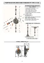
OVERALL DIMENSIONS
Approximate
net weight
kg 2.0÷2.5
Lev el switch
3
4
2
1
1
Fig.16
Fig.15


