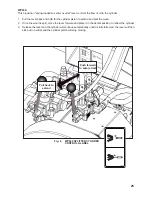
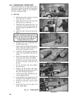
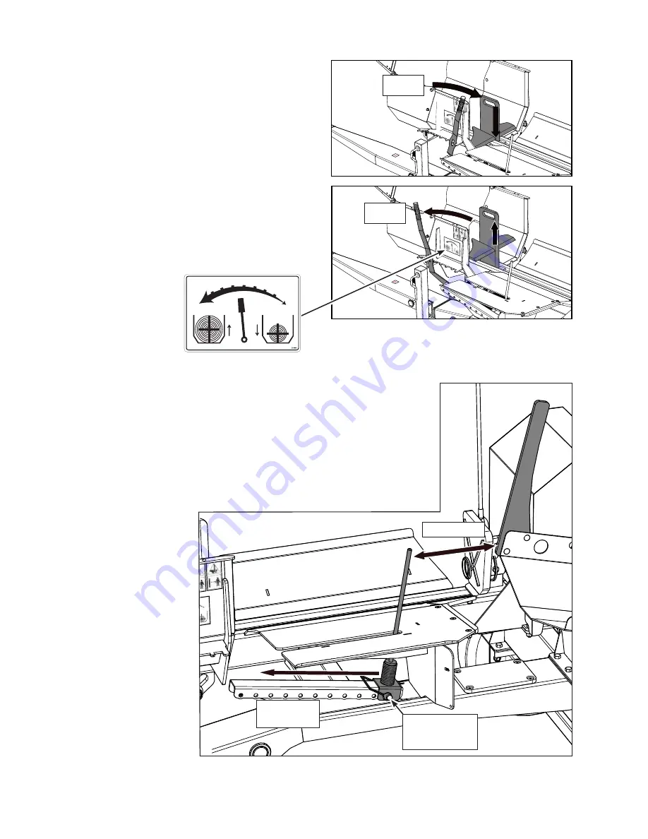
background image

26

tooltip

Fig.  10  LOG 

LENGTH

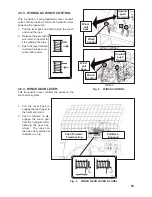
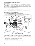
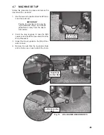
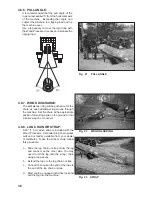
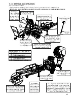
Fig.  9     SPLITTING WEDGE HEIGHT LEVER

4.5.6. SPLITTING WEDGE HEIGHT LEVER:

This multi-position lever controls and sets the

height position of the horizontal splitting wedge. 

At its lowest position the 4 way wedge becomes a 

two way wedge, to handle smaller logs, increasing 

the height allows for 4 way splitting of larger logs. 

Adjust the height as required.
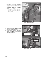
1.  Pull the lever out slightly to clear the adjustment 

cogs, then move the lever towards the engine 

to lower the splitter wedge. 

2.  To raise the wedge, pull the lever out slightly to 

clear the adjustment cogs, then move the lever 

away from the engine.

3.  For even sized splits, align the centre wedge 

with the centre of the log.

Lever Label

Measure

Lower

Raise

Move the 

guide

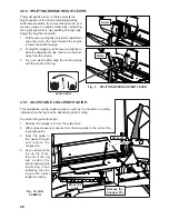
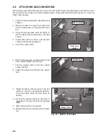
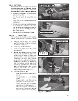
4.5.7.  ADJUSTABLE LOG LENGTH GUIDE:

This adjustable, spring loaded guide is used by the operator to quickly 

indicate when the log is at the desired length for cutting.  

To position the guide to length: 
1.  Remove the snapper pin from the guide base 
2.  With a tape measure, measure from the saw guide to the rod on the 

log length guide.

3.  Move the guide to 

the desired length 

and replace the 

snapper pin.  

4.  As you advance the 

log up the chute, 

the end of the log 

will contact the 

spring loaded guide 

rod,moving it and 

indicating that the 

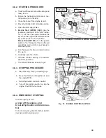
log is at the correct 

length for cutting. 

Remove the 

Snapper Pin

Summary of Contents for Wallenstein WP630

Page 1: ... CANADA Rev 300112 PART NUMBER Z97062 EMB Manufacturing Inc 4144 Boomer Line St Clements On N0B 2M0 Canada Ph 519 699 9283 Fax 519 699 4146 www embmfg com WP630 WP830 WP860 Wood Processor MODEL WP630 WP830 WP860 OPERATOR S MANUAL ...

Page 2: ...AUTO CYCLE 24 4 5 6 SPLITTING WEDGE HEIGHT LEVER 26 4 5 7 ADJUSTABLE LOG LENGTH GUIDE 26 4 5 8 SPLITTER CHUTE HEIGHT ADJUSTER 27 4 6 ATTACHING AND UNHOOKING 28 4 7 MACHINE SET UP 29 4 8 FIELD OPERATION 32 4 8 1 PREPARE 32 4 8 2 STARTING PROCEDURE 33 4 8 3 STOPPING PROCEDURE 33 4 8 4 EMERGENCY STOPPING 33 4 8 5 PROCESSING OPERATION 34 4 8 6 PULL ANGLE 36 4 8 7 WOOD DISCHARGE 36 4 8 8 LOG CHAIN OR S...

Page 3: ...ice contact your local engine dealer Under no circumstances will the manufacturer be liable for any consequential damage or expense of any kind including loss of profits The manufacturer is under no circumstances liable for tow vehicle of any kind The manufacturer is not liable for the maintenance of the product This warranty is extended only to the original purchaser and is not transferable Warra...

Page 4: ...above equipment and Operator s Manual have been received by me and I have been thoroughly instructed as to care adjustments safe operation and applicable warranty policy This form must be filled out by the dealer and signed by both the dealer and the customer at the time of deliv ery Customer s Name Dealer Name Address Address City State Province Code City State Province Code Phone Number Phone Nu...

Page 5: ...equesting service or other information The serial number plate is located where indicated Please mark the number in the space provided for easy reference SERIAL NUMBER LOCATION Wood Processor Serial Number ______________________________________ Model Number_____________________________________________________ Location Typical ...

Page 6: ...ined within the Operator s Manual This manual covers the Wallenstein Wood Processor Model WP630 WP830 WP860 Use the Table of Contents or Index as a guide to locate required information Keep this manual handy for frequent reference and to pass on to new operators or owners Call your Wal lenstein dealer or the Distributor if you need assistance information or additional copies of the manuals OPERATO...

Page 7: ...9 9283 or Fax 519 699 4146 DANGER Indicates an imminently hazardous situation that if not avoided will result in death or serious injury This signal word is to be limited to the most ex treme situations typically for machine components which for functional pur poses cannot be guarded WARNING Indicates a potentially hazardous situ ation that if not avoided could result in death or serious injury an...

Page 8: ...em Most accidents can be avoided A person who has not read and understood all using and safety instructions is not qualified to use the machine An untrained operator exposes himself and bystanders to possible serious injury or death Do not modify the equipment in any way Un authorized modification may impair the function and or safety and could affect the life of the equipment Think SAFETY Work SA...

Page 9: ...ng with work their physical limitations need to be recognized and accom modated 7 Never exceed the limits of a piece of machinery If its ability to do a job or to do so safely is in question DON T TRY IT 8 Do not modify the equipment in any way Un authorized modification may result in serious injury or death and may impair the function and life of the equipment 9 In addition to the design and conf...

Page 10: ... machine An untrained operatorexposeshimselfandbystanderstopos sible serious injury or death If the elderly are assisting with the work their physical limitations need to be recognized and accommodated 2 4 SAFETY TRAINING 2 5 PREPARATION 1 Never use the machine until you have read and completely understand this manual the engine Operator s Manual and each of the Safety Mes sages found on the safet...

Page 11: ...raulic system are kept in good condition and are clean 2 Before applying pressure to the system make sure all components are tight and that lines hoses and couplings are not damaged 3 Do not attempt any makeshift repairs to the hydraulic lines fittings or hoses by using tapes clamps or cements The hydraulic system op erates under extremely high pressure Such repairs will fail suddenly and create a...

Page 12: ...thanonelogatatime The extra log can be ejected and cause injury 9 Keep your fingers and hands away from cracks in the log that can open or close while splitting 10 Always handle logs by holding onto the sides not the top and bottom 11 Do not load the splitting cradle while the wedge is in motion 12 Do not try to split logs across the grain Some logs can burst or splinter and fly out of the ma chin...

Page 13: ...ntact flush thoroughly with water and get promptmedical attention especiallyifyoureyes are affected 3 Wear safety glasses when working near bat teries 4 Do not tip batteries more than 45 to avoid electrolyte loss 5 To avoid injury from spark or short circuit dis connect battery ground cable before servicing any part of the electrical system 6 Charge the battery in a fully ventilated location 7 Be ...

Page 14: ... engine starts 15 DO NOT strike flywheel with a hard object or metal tool as this may cause flywheel to shatter in operation Use proper tools to service engine 16 DO NOT operate engine without a muffler Inspect periodically and replace if necessary If engine is equipped with a muffler deflector inspect periodically and replace if necessary with correct deflector 17 DO NOToperate engine with an acc...

Page 15: ... else to use this Wood Processor until such information has been reviewed An nually review this information before the season start up Make these periodic reviews of SAFETY and OPERATION a standard practice for all of your equipment We feel that an untrained operator is unqualified to use this machine A sign off sheet is provided for your record keeping to show that all personnel who will be worki...

Page 16: ...dealer 3 SAFETY SIGN LOCATIONS The types of safety signs and locations on the equipment are shown in the illustrations that follow Good safety requires that you familiarize yourself with the various safety signs the type of warning and the area or particular function related to that area that requires your SAFETY AWARENESS Think SAFETY Work SAFELY Z94119 Z94123 Z94114 Z94124 Z94167 ...

Page 17: ...hile pulling Do not touch rope during operation Check rope condition before using winch Rope may break during operation if it is cut knotted hasbrokenstrandsorworn Replace rope if damaged Neverusealcoholicbeveragesordrugswhich can hinder alertness or coordination while operating this equipment Consult your doc tor about operating this machine while taking prescription medications Operate only on l...

Page 18: ...or to become familiar with control function and machine response c When a new operator is familiar and com fortable with the machine they can proceed with the work Do not allow untrained operators to use the machine They can endanger themselves and others or dam age property and the machine Job Site It is the responsibility of the operator to be thoroughly familiar with the work site prior to star...

Page 19: ...he chain saw to cut the log to the desired length When the log is cut it rolls onto the splitting cra dle Engaging the hy draulic splitter levers causes the hydraulic cylinder to push the log through the 4 way wedge The Push block loca tor indicates to the op erator where the push block is at all times Power to drive the machine is provided through the gas en gine and hydraulic pump Subaru Gas Eng...

Page 20: ...ssor requires that each operator reads and understands the using procedures and all related safety precautions outlined in this section A pre operation checklist is provided for the operator It is important for both the personal safety and maintain ing good mechanical condition that this checklist is followed BeforeoperatingtheWoodProcessorandeachtime thereafter the following areas should be check...

Page 21: ...he last spring loaded detent position to engage the starter solenoid and start the engine Release the key when the engine starts and it will return to the RUN position b Choke This push pull knob controls the position of the choke Pull the knob out to close the choke for starting when the engine is cold Push the knob in to open the choke as the engine warms Always push the knob fully in when opera...

Page 22: ...sh the lever fully in when operating the machine c Throttle This lever controls the engine RPM Turn the lever clockwise to increase engine speed and counter clockwise to decrease d Fuel Shut Off Valve This lever controls the fuel valve for the flow of fuel to the engine Flip the lever to the horizontal position to turn the fuel off and vertical to turn the fuel on e Starting Rope This retracting r...

Page 23: ...he lever forward to allow the rope to un wind under power Push Forward Freewheeling Pull Back Engaged Fig 6 WINCH GEAR LEVER LABEL Wind pull back Unwind push forward Winch Control Winch Control 4 5 4 WINCH GEAR LEVER This two position lever controls the gears on the winch drive system 1 Pull the lever back to engage the winch gear to the hydraulic motor 2 Push it forward to dis engage the winch ge...

Page 24: ...t to neutral and automatically stop the cylinder Lever 2 controls the second half of the cylinders auto cycle 1 Pull it back into detent and the cylinder will start to retract automatically 2 When the cylinder has fully retracted the lever will kick out to neutral and automatically stop the cylinder Pull both levers back into the detent position to initiate the splitting cycle The cylinder will fu...

Page 25: ...he wood 2 Once the wood is split move the lever forward and place it in the detent position to retract the cylinder 3 Release the lever and the cylinder will continue automatically until it is fully retracted the lever will then kick out to neutral and the cylinder piston will stop moving Pull back to extend Push forward to auto retract Fig 8 WP630 SPLITTER CYLINDER CONTROL LABEL ...

Page 26: ...djustment cogs then move the lever away from the engine 3 For even sized splits align the centre wedge with the centre of the log Lever Label Measure Lower Raise Move the guide 4 5 7 ADJUSTABLE LOG LENGTH GUIDE This adjustable spring loaded guide is used by the operator to quickly indicate when the log is at the desired length for cutting To position the guide to length 1 Remove the snapper pin fr...

Page 27: ... high sided dumper with out any extra handling To adjust the splitter chute height 1 Lift the splitter chute slightly to take pressure off of the adjuster 2 Remove the latch pin that secures hitch pin 3 Pull out the hitch pin that holds the adjuster in place 4 Raise the splitter chute to the required height line up the hitch pin holes and replace the hitch pin 5 Secure the hitch pin with the latch...

Page 28: ... ball hitch on the tow vehicle 4 Slowly back the tow vehicle until the hitch coupler and the ball are aligned 5 Open the coupler latch 6 With the drop leg jack lower the trailer so the hitch coupler hitches over the ball 7 Flip the coupler latch to lock the coupler around the ball 8 Install the snapper pin through the coupler latch 9 Attach the safety chain securely to the tow vehicle to prevent u...

Page 29: ...ine so the prevail ing wind breeze blows the exhaust gases fumes away from the opera tor s station Left and right Anchor Bolts 2 Crank the drop leg jacks to raise the hitch coupler and unhook the tow vehicle from the Wood Processor 3 Adjust the drop leg jacks so the Wood Proc essor is level 4 Remove the nuts from the log loader chute anchor bolts one on each side of the chute Right Side Anchor Bol...

Page 30: ... Jacks Chute Lock Arm Latch Pin 5 Remove the snapper pins securing the bracing jacks and turn them to the bracing position 6 Replace the snapper pins to secure the jacks 7 Remove the latch pin that holds the chute lock arm to the log loader chute 8 Pull the lock arm away from the chute and swing it down Secure it to the side of the frame with the latch pin ...

Page 31: ...e quired height crank the bracing jacks so they are firmly on the ground but ensure the front lip of the lead in chute is on the ground to avoid catching on logs If required ad just the drop leg jacks so the lead in chute is level with the ground and the bracing jacks have a firm grip Anchor Bolt Nuts left right Jack Feet Winch Hook Log Stabilizer Chain 16 Move the wagon trailer or conveyor into p...

Page 32: ...ss or coordination while operating this equipment Consult your doc tor about operating this machine while taking prescription medications Operate only on level ground Do not exceed winching angle of more than 25 horizontally to avoid tipping Alwayswinchupaslope Donotwinchacross a slope Do not operate on hillsides or when working area is cluttered wet muddy or icy to prevent slipping and tripping U...

Page 33: ...the rope sharply to start the engine g Run the engine for a few minutes to allow it to warm h Gradually open the choke i Increase throttle setting to maximum speed for operation j The Wood Processor is ready to go 4 8 3 STOPPING PROCEDURE a Stop winching cutting or splitting logs b Move the throttle to idle position to slow the engine RPM c Set all hydraulic controls to neutral d Turn off the igni...

Page 34: ...l sustain damage while dragging along the ground e Engage winch drive mechanism with the winch gear lever f Use the winch to pull log into log lead in chute Ensurethelogdoesnotcatchon the front lip of the lead in chute g Continue to winch the log up log loader chute to the log stabilizer and stop the winch h Ensure the log is stable disengage the winch gear pull out the rope slightly i Detach the ...

Page 35: ...ot catch on the front lip of the lead in chute 7 Continue to winch the log up to the first log 8 Use the second log to push the first one up to the cutting guide 9 After a few cuts reposition the winch strap to the far end of the second log and continue winching and cutting End of First Log Second Log Push First Log Last Log Leaver the Peavey C Last log As you finish the last log you will find it ...

Page 36: ...appropriate position for making a pile on the ground or into a trailer wagon or conveyor 4 8 8 LOG CHAIN OR STRAP A 60 1 5 m winch strap is included with the Wood Processor A standard log chain works well and is readily available from your dealer or distributor To use the strap or chain follow this procedure a Slide the log chain or strap under the log and connect on the other side You may need to...

Page 37: ...er of the log b Cut the log with the chain saw c Let the cut log roll into the splitting cradle split the wood d WP830 and WP860 Pull both split ting control levers back into detent The splitting ram will begin the auto cycle extend split the wood and retract au tomatically The control levers reset to neutral when the auto cycle completes WP630 the operator must pull back and hold the hydraulic le...

Page 38: ...ic in all situations including narrow bridges intersections etc Watch for traffic when operating near or crossing roadways Never allow riders on the machine Fig 25 TRANSPORTING When transporting the machine review and fol low these instructions 1 Clear the area of bystanders especially small children 2 Check that all the lights and reflectors required by the highway authorities are in place clean ...

Page 39: ...edure before storing 2 Remove all material from the machine 3 If storing for more than 1 month discharge fuel to prevent gum in the fuel system and carburettor parts 4 Thoroughly wash the machine with a pres sure washer or water hose to remove all dirt mud or debris 5 Inspect all moving parts for entangled mate rial Remove all entangled material 6 Check the condition of winch rope Replace or adjus...

Page 40: ...connec tions are properly secured to ensure unit is in a safe condition When completing a maintenance or service function make sure all safety shields and devices are replaced before returning unit to service 5 SERVICE AND MAINTENANCE 5 1 SERVICE 5 1 1 FLUIDS AND LUBRICANTS 1 Engine Oil Refer to the engine manufacturer s manual for maintenance and service information 2 Grease Use an SAE multi purp...

Page 41: ...s 50 hrs or Annually Winch Upper Right Log Stabilizer Upper Left Log Stabilizer Lower Right Log Stabilizer Lower Left Log Stabilizer Wedge Adjustment Arm Bushing 3 4 2 5 Optimum Level Hydraulic Filter re place every 100 hrs or annually Every 100 hrs or annually wash and clean the Wood Proces sor remove entangled material wood chips small debris 1 6 Tire Pressure check every 100 hrs or an nually On...

Page 42: ... e v e l A i r C l e a n e r H y d r a u l i c O i l L e v e l E n g i n e O i l G r e a s e F r a m e S l i d e H i n g e s P i v o t P o i n t s T i r e P r e s s u r e H y d r a u l i c O i l F i l t e r E n g i n e A i r C l e a n e r C l e a n M a c h i n e 5 1 4 SERVICE RECORD CHART See Lubrication and Maintenance sections for details of service Copy this page to continue record Refer to you...

Page 43: ...om hose and strainer 11 Fill the reservoir with 26 L of Dexron III hydr raulic oil 12 Run the machine for 1 2 minutes while op erating cylinder and check filter head for oil leaks 13 If leaks are found around the filter tighten slightly Repeat step 9 14 Check hydraulic reservoir oil level Top up as required 15 Dispose of the spilled oil in an approved container Fig 27 HYDRAULIC SYSTEM FILTER 9 0 H...

Page 44: ...uired with detent on valve Ensure machine is off and call hydraulic technician Hydraulic fluid too cold Allow machine to warm up Hydraulic fluid is too old or contaminated Change hydraulic fluid and filter Ensure machine is off and cooled down Control handle goes to neutral before rod is fully retracted Detent set too loose Call technician adjustment required with detent on valve Ensure machine is...

Page 45: ...ions Extended LxWxH 238 x 62 x 72 6 0m x 1 6m x 1 8m 210 x 62 x 72 5 3m x 1 6m x 1 8m 210 x 62 x 72 5 3m x 1 6m x 1 8m Dimensions Folded LxWxH 150 x 62 x 72 3 8m x 1 6m x 1 8m 122 x 62 x 72 3 1m x 1 6m x 1 8m 122 x 62 x 72 3 1m x 1 6m x 1 8m Winch Winch Rope Length Winch Pulling Force Discharge Chute Height Hydraulic Fluid Capacity Winch Strap Torflex Suspension 54 1 4 m Max 2 50mm Ball Coupler Sa...

Page 46: ...es by 5 Torque value for bolts and capscrews are identified by their head markings 1 4 8 6 12 9 17 12 5 16 13 10 25 19 36 27 3 8 27 20 45 33 63 45 7 16 41 30 72 53 100 75 1 2 61 45 110 80 155 115 9 16 95 60 155 115 220 165 5 8 128 95 215 160 305 220 3 4 225 165 390 290 540 400 7 8 230 170 570 420 880 650 1 345 225 850 630 1320 970 Bolt Torque SAE 2 N m lb ft SAE 5 N m lb ft SAE 8 N m lb ft Bolt Di...

Page 47: ... one wrench on the connector body and with the second tighten the swivel nut to the torque shown The torque values shown are based on lubricated connections as in reassembly Tube Size OD Nut Size Across Flats in in N m lb ft Flats Turn 3 16 7 16 8 6 1 1 6 1 4 9 16 12 9 1 1 6 5 16 5 8 16 12 1 1 6 3 8 11 16 24 18 1 1 6 1 2 7 8 46 34 1 1 6 5 8 1 62 46 1 1 6 3 4 1 1 4 102 75 3 4 1 8 7 8 1 3 8 122 90 3...

Page 48: ...YLON CHAINSAW HOLSTER For models WP630 WP830 WP860 easy to install in minutes and you re ready to go 6 way splitting wedge Boost your productivity and make quick work out of chunks by splitting into six pieces at once This is an ideal way to save time 2089W571 6 WAY WEDGE 2089A570 2089W571 Helps to move those heavy log timbers into position and finish getting your last logs through the Wood Proces...

Page 49: ...41 L LAST LOG 35 LOCK ARM 30 LUBRICANTS 40 O OPERATION 17 P PEAVEY 48 PPE 32 S SAFETY 7 BATTERY 13 EQUIPMENT 9 GAS MOTOR 14 GENERAL 8 HYDRAULIC 11 MAINTENANCE 11 OPERATING 12 PREPARATION 10 REFUELLING 13 SAFETY SIGNS 9 STORAGE 13 TIRE 13 TRAINING 10 TRANSPORT 11 SAFETY SIGN 16 SECOND LOG 35 SERIAL NUMBER 5 SERVICE AND MAINTENANCE SERVICE ILLUSTRATION 41 SERVICE RECORD CHART 42 SIGN OFF FORM 15 SPE...

Reviews: