

SMARC T335x Carrier Board Hardware Design Guide, Document Revision 1.2
Floor Planning the PCB
This Chapter gives mechanical information needed when
designing the SMARC carrier board. Section include
:
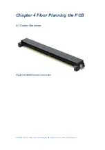
Carrier
Connector
Module and Carrier Connector Pin Numbering
Convention
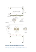
Module Outline – 82mm x 50mm Module
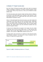
Module “Z” Height Consideration
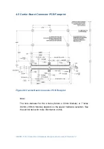
Carrier Board Connector PCB Footprint
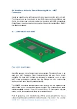
Module and Carrier Board Mounting Holes – GND
Connection
Carrier Board Standoffs