


SMARC T335x Carrier Board Hardware Design Guide, Document Revision 1.2
Chapter 2 Interfaces
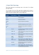
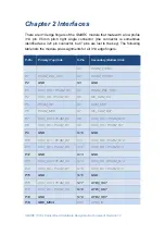
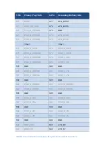
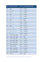
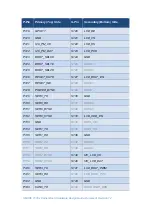
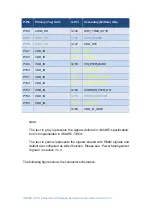
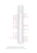
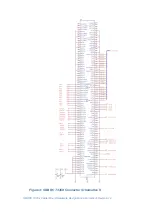
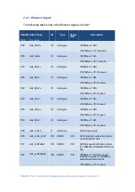
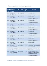
There are 314 edge fingers of the
SMARC
module that mate with a low profile
314 pin 0.5mm pitch right angle connector (the connector is sometimes
identified as a 321 pin connector, but 7 pins are lost to the key). The following
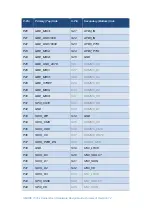
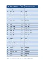
table lists the module pin assignments for all 314 edge fingers.
P-Pin
Primary (Top) Side
S-Pin
Secondary (Bottom) Side
S1
PCAM_VSYNC
P1
PCAM_PXL_CK1
S2
PCAM_HSYNC
P2
GND
S3
GND
P3
/ PCAM_D0
S4
PCAM_PXL_CK0
P4
CSI1_CK- / PCAM_D1
S5
I2C_CAM_CK
P5
PCAM_DE
S6
CAM_MCK
P6
PCAM_MCK
S7
I2C_CAM_DAT
P7
/ PCAM_D2
S8
/ PCAM_D10
P8
CSI1_D0- / PCAM_D3
S9
CSI0_CK- / PCAM_D11
P9
GND
S10
GND
P10
/ PCAM_D4
S11
/ PCAM_D12
P11
CSI1_D1- / PCAM_D5
S12
CSI0_D0- / PCAM_D13
P12
GND
S13
GND
P13
/ PCAM_D6
S14
/ PCAM_D14
P14
CSI1_D2- / PCAM_D7
S15
CSI0_D1- / PCAM_D15
P15
GND
S16
GND
P16
/ PCAM_D8
S17
AFB0_OUT
P17
CSI1_D3- / PCAM_D9
S18
AFB1_OUT
P18
GND
S19
AFB2_OUT
P19
GBE_MDI3-
S20
AFB3_IN