
SMARC T335x Carrier Board Hardware Design Guide, Document Revision 1.2
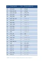
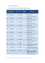
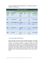
2.2.1. Ethernet Signal
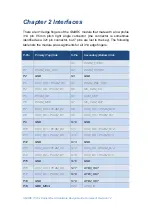
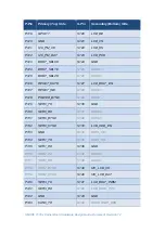
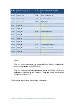
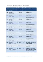
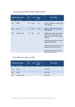
The following table shows the Ethernet signals of
LAN1
.
SMARC Edge Finger
I/O
Type
Power
Rail
Description
Pin#
Pin
Name
P30
G
IO
Analogue
1000Base-T: DA+
10/100Base-TX: Tr
P29
GBE_MDI0
‐
IO
Analogue
1000Base-T: DA-
10/100Base -TX: Transmit -
P27
G
IO
Analogue
1000Base-T: DB+
10/100Base -TX: R
P26
GBE_MDI1
‐
IO
Analogue
1000Base-T: DB-
10/100Base -TX: Receive -
P24
G
IO
Analogue
1000Base-T: DC+
10/100Base -TX: Unused
P23
GBE_MDI2
‐
IO
Analogue
1000Base-T: DC-
10/100Base -TX: Unused
P20
G
IO
Analogue
1000Base-T: DD+
10/100Base -TX: Unused
P19
GBE_MDI3
‐
IO
Analogue
1000Base-T: DD-
10/100Base -TX: Unused
P28
GBE_CTREF
O
Analogue
Centre tap supply
P25
GBE_LINK_ACK#
OD
CMOS
3.3V
LED indication output for activity
on the Ethernet port
P21
GBE_LINK100#
OD
CMOS
3.3V
LED link speed indication output
for 100Mbps established Ethernet
link
P22
GBE_LINK1000#
OD
CMOS
3.3V
1000Base-T: LED link speed
indication output for 1000Mbps
established Ethernet link
10/100Base -TX: Unused