


SMARC T335x Carrier Board Hardware Design Guide, Document Revision 1.2
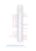
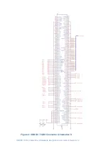
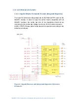
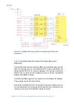
2.2.3. LAN Reference Schematic
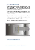
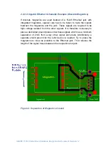
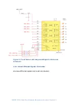
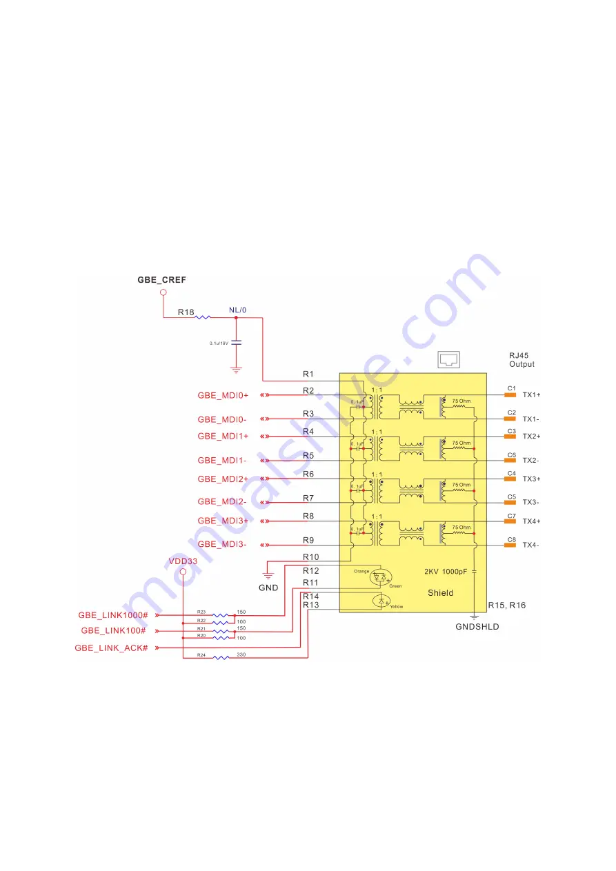
2.2.3.1. Gigabit Ethernet Schematic Example (Integrated Magnetics)
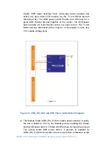
The need for centre tap voltage depends on the Ethernet
PHY
used on the
SMARC
module. In order to keep the carrier board compatible with all
SMARC
modules, the centre tap pins of the magnetics should all be
connected to the centre tap voltage source pin of the module connector
(
GBE_CTREF
). Please add a ferrite bead and capacitors according to the
reference schematic.
Figure 8: Gigabit Ethernet with Integrated Magnetics Reference
Schematic