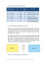
SMARC T335x Carrier Board Hardware Design Guide, Document Revision 1.2
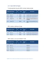
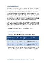
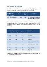
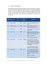
I2C_GP
interface signal is defined as follows.
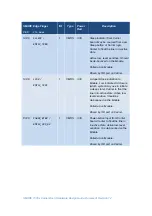
SMARC Edge Finger
I/O
Type
Power
Rail
Description
Pin#
Pin
Name
S48
I2C_GP_CK
IO
OD
CMOS
3.3V
General purpose use
S49
I2C_GP_DAT
IO
OD
CMOS
3.3V
General purpose use
Both
I2C_GP_CK
and
I2C_GP_DAT
have a 2.2k pull-up resistor to 3.3V.
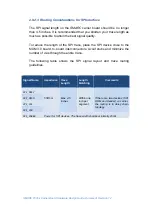
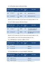
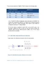
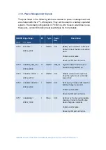
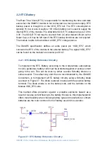
I2C_LCD
interface signal is defined as follows.
SMARC Edge Finger
I/O
Type
Power
Rail
Description
Pin#
Pin
Name
S48
I2C_GP_CK
IO
OD
CMOS
3.3V
LCD display support (for
parallel and LVDS LCD)
S49
I2C_GP_DAT
IO
OD
CMOS
3.3V
LCD display support (for parallel
and LVDS LCD)
Both
I2C_GP_CK
and
I2C_GP_DAT
have a 2.2k pull-up resistor to 3.3V.
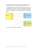
All I2C interfaces can be served as general purpose I2C bus.
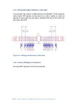
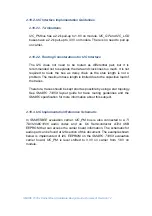
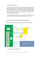
I2C_CAM
interface is not used in
SMARC T335X.
SMARC Edge Finger
I/O
Type
Power
Rail
Description
Pin#
Pin
Name
S5
I2C_CAM_CK
Not Used
S6
I2C_CAM_DAT
Not Used
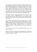
I2C for HDMI
interface is not used in
SMARC T335X
either.
SMARC Edge Finger
I/O
Type
Power
Rail
Description
Pin#
Pin
Name
P104
HDMI_CTRL_CK
Not Used
P105
HDMI_CTRL_DAT
Not Used