


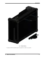
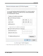
Veronte PCS
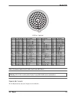
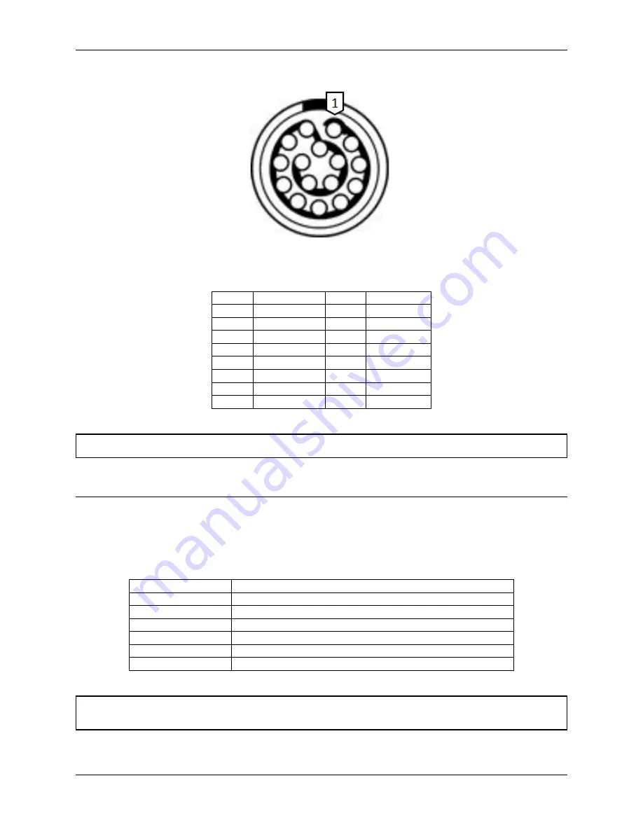
PCS Unit - Output pins
Pin nº Function
Pin nº Function
1
3.3V (Output)
9
Not used (*)
2
GND
10
Not used (*)
3
5V (Output)
11
Not used (*)
4
GND
12
Not used (*)
5
12V (Output)
13
CANA_P
6
GND
14
RS232-TX
7
24V (Output)
15
CANA_N
8
GND
16
RS232-RX
Warning:
RS-232 pins are common with the external pinnout.
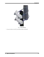
The Expansion Bay mating connector is EGG.2B.316.CLL.
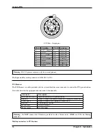
PCS Harness
The PCS Harness is a cable provided with the system which has many connectors to control the PCS ground station.
Next table describes the equipped connectors and its functionality.
Connector
Description
FGW.LM.368.XLCT Main connector to PCS ground station
Ethernet
Ready to connect an Ethernet cable to a Laptop or Veronte MCS
USB Type A
Ready to connect to a Laptop or Veronte MCS
Joystick
PPM input for Joystick
Push button
ON/OFF button
Power source
24 VDC input
Warning:
Do
NOT
connect the CS harness provided for other Veronte units.
ONLY
use PCS own Matting
connector.
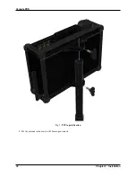
Matting connectors to PCS harness
14
Chapter 2. Installation
Summary of Contents for Veronte PCS
Page 1: ...Veronte PCS Embention Apr 21 2022 ...
Page 2: ......
Page 4: ...ii ...
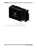
Page 8: ...Veronte PCS Fig 2 System Dimensions 4 Chapter 1 Technical ...
Page 10: ...Veronte PCS 1 6 Interfaces Fig 4 PCS Interfaces Parts identification 6 Chapter 1 Technical ...
Page 11: ...Veronte PCS Fig 5 PCS Interfaces Parts identification 1 6 Interfaces 7 ...
Page 14: ...Veronte PCS 10 Chapter 1 Technical ...
Page 24: ...Veronte PCS 20 Chapter 2 Installation ...
Page 36: ...Veronte PCS Fig 4 Basic Features Veronte PCS 32 Chapter 4 Maintenance ...


