Veronte PCS
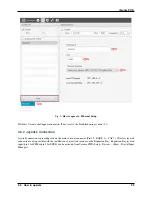
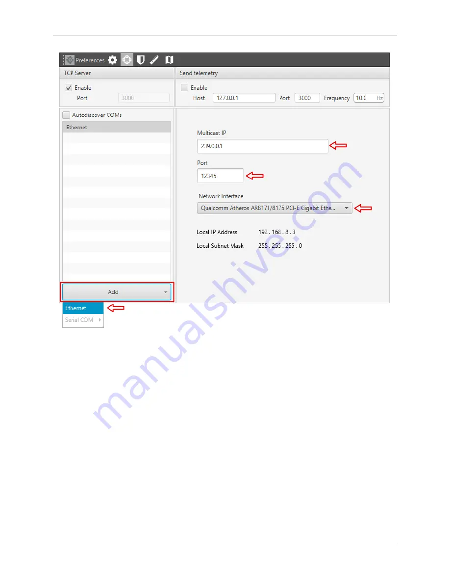
Fig. 2:
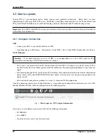
How to operate - Ethernet Setup
With this, Veronte shall appear connected. If not, refer to the Troubleshooting section (4.1).
3.3.2 Joystick Connection
Joystick connection is preconfigured on the main external connector (Pin 55 - EQEP_A – CAP 1). Wireless joystick
connection is also possible with the installation of a joystick receiver on the Expansion Bay. Expansion Bay joystick
input (pin 8 for PPM or pin 9 for SBUS) can be activated from Veronte PIPE (Setup – Devices – Others – Digital Input
Manager).
3.3. How to operate
23
Summary of Contents for Veronte PCS
Page 1: ...Veronte PCS Embention Apr 21 2022 ...
Page 2: ......
Page 4: ...ii ...
Page 8: ...Veronte PCS Fig 2 System Dimensions 4 Chapter 1 Technical ...
Page 10: ...Veronte PCS 1 6 Interfaces Fig 4 PCS Interfaces Parts identification 6 Chapter 1 Technical ...
Page 11: ...Veronte PCS Fig 5 PCS Interfaces Parts identification 1 6 Interfaces 7 ...
Page 14: ...Veronte PCS 10 Chapter 1 Technical ...
Page 24: ...Veronte PCS 20 Chapter 2 Installation ...
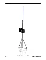
Page 36: ...Veronte PCS Fig 4 Basic Features Veronte PCS 32 Chapter 4 Maintenance ...


