2-14
Setting Up and Starting a CX700 System
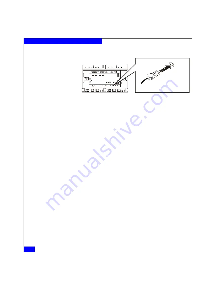
Figure 2-8
Connecting the Copper Cable to the BE 0 SP Port
4. To connect additional DAEs on each loop, cable the LCC EXP
(expansion) port on each DAE to the PRI port on the next LCC
on
that loop
. Be sure to maintain the division between A and B
components; never connect an LCC A and an LCC B together.
Note that in a typical single-cabinet installation, loops skip over physically
adjacent DAEs, as shown in Figure 2-9. Other configurations allow
daisy-chaining between adjacent DAEs, as shown in Figure 2-11.
You can mix DAE2 and DAE2P enclosures in a storage system and along a
loop.
Figures 2-9 through 2-12 show sample SPE-to-DAE loops, enclosure
addresses, and cabling in one- and two-cabinet configurations.
EMC2293
To other FC device
BE 0
Connector
Summary of Contents for CLARiiON CX700
Page 4: ...CX700 Hardware Reference iv ...
Page 8: ...CX700 Hardware Reference viii Contents ...
Page 18: ...xviii CX700 Hardware Reference Warnings and Cautions ...
Page 56: ...2 26 CX700 Hardware Reference Setting Up and Starting a CX700 System ...
Page 74: ...3 18 CX700 Hardware Reference Servicing a CX700 SPE ...
Page 96: ...A 18 CX700 Hardware Reference Technical Specifications and Operating Limits ...
Page 104: ...B 8 CX700 Hardware Reference Customer Support ...


