1-8
EMC CX200-Series DPE2 Hardware Reference
About the CX200-Series DPE2
The storage processor communicates with internal disks through the
midplane. It connects to external link control cards (LCCs) and disks
via an external FC-AL loop (bus). The SP-LCC interface is called the
SP back end.
On a highly available CX200 system, you can replace either storage
processor module while the CX200 is running. Since a CX200LC
system does not include redundant SPs, failure or removal of the
single SP will cause a system failure.
You should never attempt to replace any of the SP’s components.
CAUTION
!
Pulling out a CX200 SP will cause a failover. (A failover is the
automatic transfer of one or more LUNS from one SP to another, if
a failure occurs in the path of the original SP.)
CX200 SPs are paired. If you remove both storage processors
simultaneously, neither SP can save cached data to disk.
Disk Modules
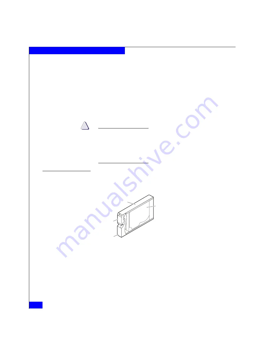
Each disk module, shown in Figure 1-8, consists of one 12-volt Fibre
Channel disk drive in a carrier. You can add or remove a disk module
while the CX200 is powered up, but you should exercise special care
when removing drives while they are in use.
Figure 1-8
Disk Module
Disk Drives
The disk drives are 3.5-inch (8.75 cm) by 1.0-inch (2.54 cm), 12-Volt,
Fibre Channel drives that conform to the following standards:
◆
SFF-8045
◆
SCSI Enclosure Services (SES) portion of the SCSI 3 Standard
◆
FC-AL
◆
FC-AL Private Loop Direct Attach (PLDA) Profile
◆
2-Gbit Fibre Channel interface
EMC1758
Carrier
Latch
Handle
Disk
Drive
Summary of Contents for CX200-Series
Page 4: ...EMC CX200 Series DPE2 Hardware Reference iv ...
Page 42: ...2 18 EMC CX200 Series DPE2 Hardware Reference Installing a CX200 Series DPE2 ...
Page 64: ...3 22 EMC CX200 Series DPE2 Hardware Reference Servicing and Upgrading a CX200 Series DPE2 ...
Page 80: ...A 12 EMC CX200 Series DPE2 Hardware Reference Technical Specifications and Operating Limits ...
Page 86: ...g 6 EMC CX200 Series DPE2 Hardware Reference Glossary ...


