6
DD640, DD670, DD860, and DD890 Disk Drive Replacement
Note:
If the amber LED is on (alert or fault) and the disk drive is also powered on (blue),
the combination of the two colors is light purple (fuchsia).
Preparing for Disk Drive Replacement
Caution:
Only trained and qualified personnel should install or replace this equipment.
Identify the failed disk drive
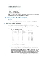
To display the disk drive hardware status, use the
disk show reliability-data
command. The display is similar to the following. The first twelve entries in the display
are the twelve disk drives in the chassis (for a DD670 system or a 12-drive DD640
system):
#
disk show reliability-data
Disk ATA Bus Reallocated Temperature
(enc/disk) CRC Err Sectors
---------- ------- ----------- -----------
1.1 0 0 32 C 90 F
1.2 0 0 32 C 90 F
1.3 0 0 32 C 90 F
1.4 0 0 32 C 90 F
1.5 0 0 33 C 91 F
1.6 0 0 33 C 91 F
1.7 0 0 32 C 90 F
1.8 0 0 31 C 88 F
1.9 0 0 33 C 91 F
1.10 0 0 33 C 91 F
1.11 0 0 33 C 91 F
1.12 0 0 32 C 90 F
---------- ------- ----------- -----------
12 drives operating normally.
Notes:
•
DD860 or DD890 output shows only information about its four disk drives. A
DD640 7-drive system shows only information about its seven disk drives.
•
Always replace a failed disk drive as soon as possible. A DD860 or DD890 system
can run with two live disk drives and no spare, but another disk drive failure
disables the system. A DD640 system has one hot spare and either 6 or 11 usable
disks in a RAID-6 configuration and a DD670 has one hot spare and 11 usable
Table 2:
Disk Drive Carrier LEDs
LED State
Description
Blue (bright) Disk drive present
Blue (dim or
blinks)
Disk drive activity
Amber
Disk drive fault
Off (not lit)
No disk drive present

