background image

Placement options

45

System Placement

Other storage bays are daisy chained together using 8-meter 
cables and can be up to five bays away from the NAS or NAS 
expansion bay with cabling under a raised floor.

DLm960 
configuration floor 
cutouts

DLm960 supports a maximum of 13 bays. 

Figure 4 on page 45


illustrates the configuration and the recommended floor tile cutouts 
for the DLm960 configuration. The illustrations assume that the floor 
tiles are 24 x 24 in. (61 x 61 cm).

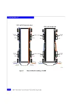
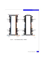
Figure 4

DLm960 configuration floor cutout

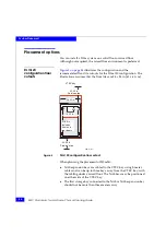
DLm4020 
configuration floor 
cutouts

Figure 5 on page 46

 illustrates the configuration and the 

recommended floor tile cutouts for the DLm4020 configuration. The 
illustrations assume that the floor tiles are 24 x 24 in. (61 x 61 cm).

NA

S

 exp

a

n

s

ion 

ba

y

NA

S


ba

y

S

tor

a

ge 

ba

y

s

S

tor

a

ge 

ba

y

s

VTEC 

ba

y

42.00 in.

S

ervice 

a

re

a

Front

GEN-001152

41.

88

 in.

Incl

u

de

s

front 

a

nd 

re

a

r door

s

8

.00 in.

6.00 in.

24.02 in.

Floor tile

s

24 in. 

sq

.

42.00 in.

S

ervice 

a

re

a

Summary of Contents for DLm120

Page 1: ...EMC Corporation Corporate Headquarters Hopkinton MA 01748 9103 1 508 435 1000 www EMC com EMC Disk Library for mainframe Physical Planning Guide P N 300 009 100 REV A03...

Page 2: ...IND WITH RESPECT TO THE INFORMATION IN THIS PUBLICATION AND SPECIFICALLY DISCLAIMS IMPLIED WARRANTIES OF MERCHANTABILITY OR FITNESS FOR A PARTICULAR PURPOSE Use copying and distribution of any EMC sof...

Page 3: ...0 19 DLm4020 19 DLm4080 20 General considerations 20 Other requirements 20 Other considerations 22 Environmental specifications 22 System host cabling requirements 22 Remote support 22 Planning for up...

Page 4: ...ecifications Physical data 38 Environmental data 39 Air flow 39 Environment acclimation 39 Power and cooling data 41 Chapter 4 System Placement Placement options 44 DLm120 configuration floor cutouts...

Page 5: ...ster and leveler dimensions 48 8 Power distribution cabling DLm120 and DLm4020 51 9 Power distribution cabling DLm960 52 10 Power distribution cabling DLm4080 53 11 EMC model number DLmP40U 60 US cabl...

Page 6: ...EMC Disk Library for mainframe Physical Planning Guide 6 Figures...

Page 7: ...y 38 4 DLm environmental data 39 5 Environmental requirements for shipping and storage 39 6 Environmental acclimation 40 7 DLm120 power consumption and heat dissipation 41 8 DLm960 power consumption a...

Page 8: ...EMC Disk Library for mainframe Physical Planning Guide 8 Tables...

Page 9: ...grounding conductors removed for or during any installation procedure Attention Res rv au personnel autoris Cet appareil EMC comporte plus d un cordon d alimentation Afin de pr venir les chocs lectriq...

Page 10: ...miliar with safety procedures for electrical equipment and EMC hardware should access components inside the unit or move the unit WARNING This product operates at high voltages To protect against phys...

Page 11: ...static discharge and need to be handled accordingly CAUTION Before handling printed circuit boards or other parts containing LSI and or VLSI components observe the following precautions Store all prin...

Page 12: ...12 EMC Disk Library for mainframe Physical Planning Guide Warnings and Cautions...

Page 13: ...f a product does not function properly or does not function as described in this document please contact your EMC representative This manual is part of the documentation set for the EMC Disk Library f...

Page 14: ...onventions used in this guide EMC uses the following conventions for notes cautions warnings and danger notices Note A note presents information that is important but not hazardous CAUTION A caution c...

Page 15: ...ch as names of windows dialog boxes buttons fields and menus What user specifically selects clicks presses or types Italic Used in all text including procedures for Full titles of publications referen...

Page 16: ...t through Powerlink you must have a valid support agreement Please contact your EMC sales representative for details about obtaining a valid support agreement or to answer any questions about your acc...

Page 17: ...to be completed when planning an installation of DLm systems at the customer site Read the information and follow the procedures in the order documented in this chapter Planning overview 18 DLm syste...

Page 18: ...anning sessions with your EMC Systems Engineer and EMC Customer Support Representative will be necessary to close all the details related to installation Table 1 on page 18 lists the responsibility su...

Page 19: ...960 DLm960 contains one VTEC bay one NAS bay an optional NAS expansion bay and up to ten storage bays When fully configured the weight of each bay is VTEC bay 874 lb 397 2 kg NAS bay 1330 lb 604 5 kg...

Page 20: ...r these factors Weight capacities of the service elevator if delivery is to another floor Availability of an equipment ramp if the receiving floor is not on level with computer room floor Note All por...

Page 21: ...gned shipping material crated and palletized For a DLm system delivered internationally EMC recommends shipment by air freight Unless otherwise instructed the EMC Traffic Department arranges for deliv...

Page 22: ...tion to the DLm From a physical planning perspective review the routing paths from the hosts to the DLm system Resolve any physical access issues prior to installation day Layout and space recommendat...

Page 23: ...DLm supports DLm120 Modems on page 27 DLm960 Modems on page 30 DLm4020 Modems on page 32 DLm4080 Modems on page 34 Note You do not need a separate phone line for each modem You can move phone lines b...

Page 24: ...24 EMC Disk Library for mainframe Physical Planning Guide Physical Planning...

Page 25: ...vity 25 2 This chapter covers the configurations and host connectivity of the DLm system DLm120 overview 26 DLm960 overview 28 DLm4020 overview 31 DLm4080 overview 33 Installation information 36 Syste...

Page 26: ...ional equipment in the DLm120 bay DLm120 system The DLm120 system contains the following Two ACPs Up to two VTEs FICON or ESCON channel adapters AHA363 compression adapters FICON VTE only Two 1 Gb Eth...

Page 27: ...k Control Cards LCC Redundant power supplies The boot DAE includes Six FC drives Two link control cards LCC Redundant power supplies Modems DLm120 ships with four modems ACPs and Control Stations supp...

Page 28: ...endent power cables each zone capable of powering a fully configured bay Chapter 5 Power Requirements contains specifications for DLm power requirements CAUTION The DLm960 VTEC NAS and storage bay equ...

Page 29: ...xpansion bay contains one network server NS960 and integrated storage arrays comprising Two to six Storage Controllers Data Movers Two Control Stations Two storage processors SPA and SPB Dual standby...

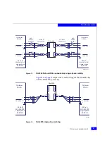
Page 30: ...f two ACPs and one network server ships with four modems A DLm960 system with an additional network server NAS expansion bay has six modems Figure 1 on page 30 shows the cable connection for DLm960 an...

Page 31: ...t enclosures and power systems are designed to support DLm4020 system equipment only EMC does not support any other components in the DLm4020 system enclosure and recommends that you do not install an...

Page 32: ...undant power supplies The boot DAE includes 6 FC drives Two LCCs Redundant power supplies Modems DLm4020 includes three or four modems ACPs and Control Stations support one modem each Each DLm network...

Page 33: ...ystem storage and expansion storage bay equipment enclosures and power systems are designed to support DLm4080 system equipment only EMC does not support any other components in these bays and recomme...

Page 34: ...Data Movers Two Control Stations Dual standby power supplies Two storage processors Up to 6 DAEs Excluding Vault DAE The DLm4080 NAS expansion bay requires four power connections DAE Each storage DAE...

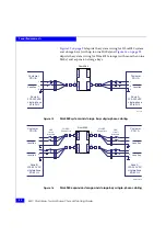
Page 35: ...es the power requirements for DLm4080 Figure 2 on page 35 shows the cable connection for DLm120 DLm4080 and DLm4020 Figure 2 Cable connection for DLm120 DLm4080 and DLm4020 ACP ACP VTE VTE Control Sta...

Page 36: ...nts Specifications Mainframe Software Operating system and version number JES2 or JES3 Channel Information Channel type Number of channels Type of channels FICON or ESCON Configuration Information LPA...

Page 37: ...hysical and Environmental Specifications 37 3 This chapter covers the physical and environmental specifications for DLm Physical data 38 Environmental data 39 Physical and Environmental Specifications...

Page 38: ...hysical specifications Table 3 DLm physical specification for single bay Description Measurements Height 76 66 in 194 7 cm a a With trim kit optional attached Width 24 02 in 61 0 cm Depth DLm 120 960...

Page 39: ...do not apply AC power to it for at least the number of hours specified in Table 6 on page 40 Table 4 DLm environmental data Condition Limits Operating temperature 50o 90o F 10o to 32o C Operating alt...

Page 40: ...itude and atmospheric pressure specifications are referenced to a standard day at 58 7 F 14 8 C Maximum wet bulb temperature is 82 F 28 C Table 6 Environmental acclimation Transit storage environment...

Page 41: ...ion Btu Hr VTEC bay 3 20 11 000 Storage bay 4 04 13 200 NAS bay b 5 72 17 200 a All VTEC bay values are calculated for a fully loaded configuration Contact your EMC Sales Representative for specific s...

Page 42: ...mainframe Physical Planning Guide Physical and Environmental Specifications a All system bay values are calculated for a fully loaded configuration Contact your EMC Sales Representative for specific s...

Page 43: ...System Placement 43 4 This chapter covers the physical placement options that are available for DLm Placement options 44 System Placement...

Page 44: ...assumes that the floor tiles are 24 x 24 in 61 x 61 cm Figure 3 DLm120 configuration floor cutout When planning the placement of DLm960 NAS expansion bays are cabled to the VTEC bay using 5 meter cab...

Page 45: ...e DLm960 configuration The illustrations assume that the floor tiles are 24 x 24 in 61 x 61 cm Figure 4 DLm960 configuration floor cutout DLm4020 configuration floor cutouts Figure 5 on page 46 illust...

Page 46: ...r mainframe Physical Planning Guide System Placement Figure 5 DLm4020 configuration floor cutout CL4259 System bay 41 16 in Includes front and rear doors 8 00 in 6 00 in 24 02 in 42 00 in Service area...

Page 47: ...Lm placement for DLm4080 ensure that The storage bays are positioned on either side of the system and the expansion storage bay The optional expansion storage bay is positioned next to the system bay...

Page 48: ...dimensions Figure 7 Caster and leveler dimensions GEN 000000 Front 2 55 in 6 48 cm 1 50 in 3 81 cm 1 50 in 3 81 cm Rear caster swivel 0 75 in 1 90 cm any direction 2 Front caster fixed 2 4 19 in 10 6...

Page 49: ...uirements for the DLm system configurations The procedures for connecting customer power to the system are also covered The major topics are DLm power requirements 50 DLm touch current compliance 59 R...

Page 50: ...for these systems Table 11 North American single phase electrical specifications Specification Requirement Input voltage 200 V AC to 240 V AC 10 10 single phase Frequency 50 Hz to 60 Hz Circuit breake...

Page 51: ...ibution cabling DLm120 and DLm4020 ON I OFF O ON I OFF O ON I OFF O ON I OFF O ON I OFF O ON I OFF O ON I OFF O ON I OFF O ON I OFF O ON I OFF O ON I OFF O ON I OFF O Power source A GEN 001127 Power s...

Page 52: ...F O ON I OFF O ON I OFF O ON I OFF O ON I OFF O ON I OFF O ON I OFF O ON I OFF O ON I OFF O ON I OFF O ON I OFF O ON I OFF O ON I OFF O Power source A CL4258 Power source B Power source A Power source...

Page 53: ...O ON I OFF O ON I OFF O ON I OFF O ON I OFF O ON I OFF O ON I OFF O ON I OFF O ON I OFF O ON I OFF O ON I OFF O ON I OFF O Power source A CL0000 Power source B Power source A Power source C Power sour...

Page 54: ...ach The DLm120 bay The DLm960 VTEC bay The DLm960 Storage bays The DLm4020 bay The DLm4080 storage bay with up to nine DAEs For these bays the upper PDUs are cabled to the lower PDPs in manufacturing...

Page 55: ...e connects to a customer supplied L6 30R or HBL2621 coupler EMC provides similar cable sets with appropriate wiring and couplers for all supported international installations Figure 11 EMC model numbe...

Page 56: ...orage bays Figure 13 on page 57 illustrates the system wiring for DLm960 NAS and NAS Expansion bays Figure 12 DLm120 bay DLm960 VTEC and storage bays single phase cabling Customer PDU B Zone B 200 240...

Page 57: ...r PDU A Zone B 200 240 V AC single phase 50 60 Hz Zone A 200 240 V AC single phase 50 60 Hz DLm 960 GEN 001147 Location Location B A L N G L N G Location Location 30A circuit breakers LG 30R connector...

Page 58: ...ing Figure 16 DLm4080 expansion storage and storage bays single phase cabling Customer PDU B Customer PDU A Zone B 200 240 VAC single phase 50 60 Hz Zone A 200 240 VAC single phase 50 60 Hz DLm4080 CL...

Page 59: ...supplies on separate Main and Auxiliary circuit panels to differential trip devices These devices are typically called Ground Fault Circuit Interrupter GFCI Ground Fault Interrupter GFI Earth Leakage...

Page 60: ...le phase currents shall be used for this calculation To measure the Protective Conductor Current the procedure for measuring Touch Current is used but the measuring instrument is replaced by an ammete...

Page 61: ...owing When you are planning the UPS solution for a DLm and the host system is presently or will potentially be protected with a UPS the battery backup time you propose for the DLm UPS solution should...

Page 62: ...62 EMC Disk Library for mainframe Physical Planning Guide Power Requirements...

Page 63: ...29 NAS expansion bay 29 overview 28 VTEC bay 28 E EMC Customer Support Representative 18 EMC Sales and Customer Support 13 environment acclimation 39 environmental data 39 H heat dissipation 41 I ins...

Page 64: ...r requirements 49 choosing a UPS 61 regulatory compliance 60 Preface 13 pre installation responsibility 18 presite considerations 19 DLm120 19 DLm960 19 general considerations 20 other requirements 20...

Reviews: