3
3-36
EMC Disk-Array Processor Enclosure (DPE) Deskside Model FC4400/4500 Hardware Reference
Servicing and Upgrading a Deskside DPE
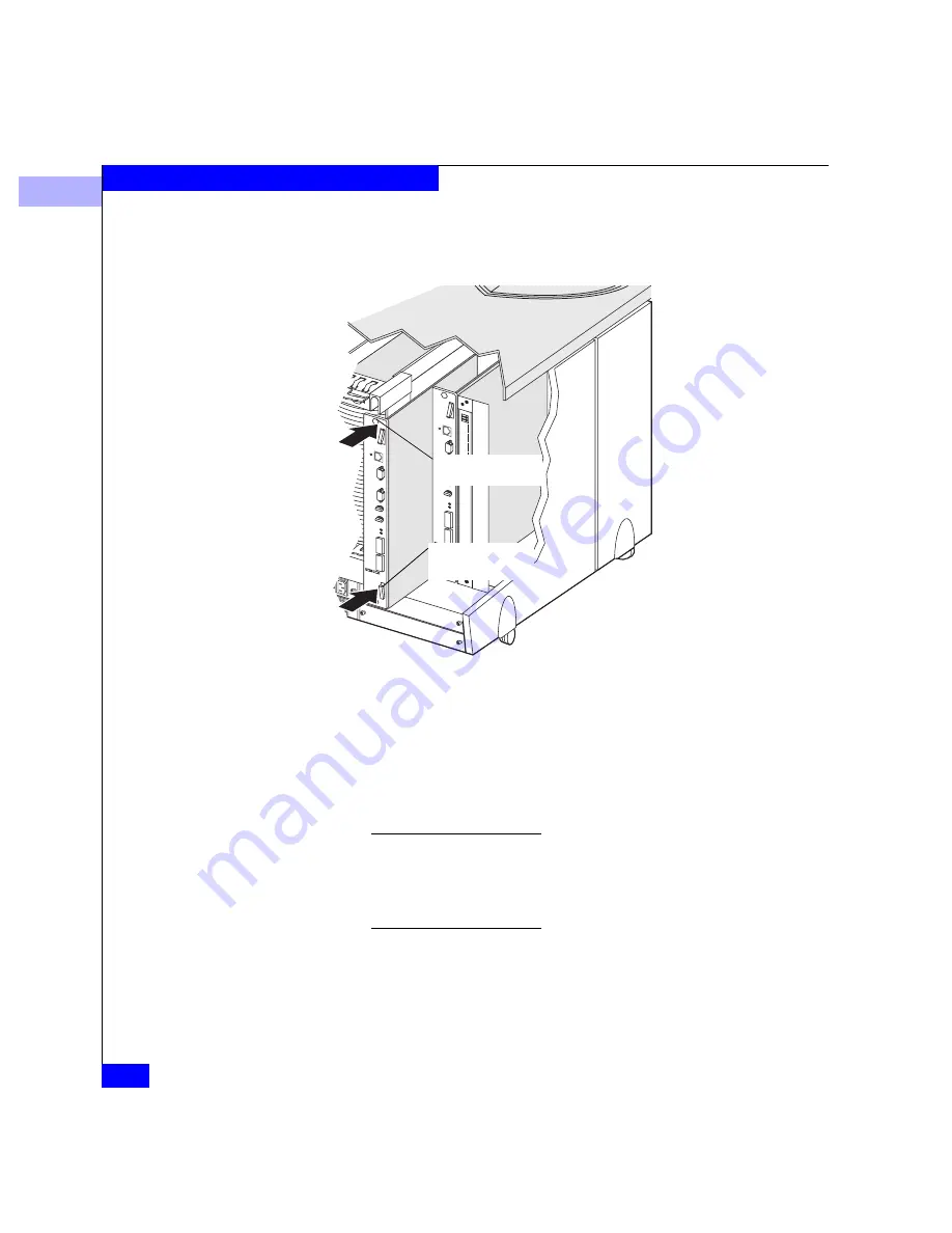
2. At the back of the deskside DPE, gently insert the SP or filler
module as shown below.
Figure 3-24
Installing an SP or SP Filler Module
If you just installed an SP filler module, you are done. Remove
and store the ESD wristband. If you just installed a replacement
or add-on SP, continue to the next step.
3. Install or reinstall the GBIC connector(s) and cables on the SP (see
An SP requires an LCC installed in the DPE and in each expansion DAE
on the corresponding loop (for example, SP A requires LCC A, and SP B
requires LCC B). If you installed an add-on SP, make sure a second LCC
is installed in the DPE enclosure and in every DAE enclosure on the
corresponding loop.
A. Open the ejectors
as far as possible;
then gently push the
module into the
enclosure guides,
supporting it at both
sides.
B. Close the ejectors.
C. Tighten the retaining
screws
Ejector
(one each side)
Retaining screw
(one each side)


