background image

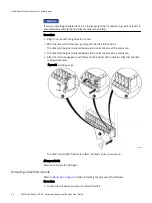
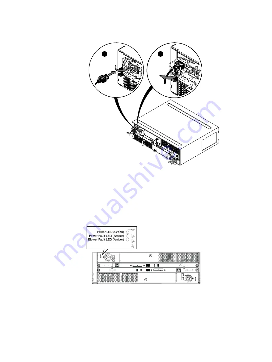
Figure 28  Plugging in and securing an AC power cord

CL4604

2

1

Verifying DAE status

Procedure

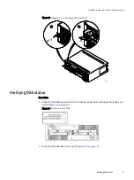
1. Verify that the DAE power LED is lit and that the power fault and blower fault LEDs are

not lit (

Figure 29 on page 51

).

Figure 29  Enclosure status LEDs

2. Verify that the DAE fault LED is not lit (

Figure 30 on page 52

).

CloudBoost Disk Array Expansion Replacement

Verifying DAE status


51

Summary of Contents for CloudBoost 100

Page 1: ...EMC CloudBoost 100 Version 2 0 Hardware Component Replacement Guide P N 302 002 471 REV 02 ...

Page 2: ... merchantability or fitness for a particular purpose Use copying and distribution of any EMC software described in this publication requires an applicable software license EMC EMC and the EMC logo are registered trademarks or trademarks of EMC Corporation in the United States and other countries All other trademarks used herein are the property of their respective owners For the most up to date re...

Page 3: ...perating Limits 21 Fire suppressant disclaimer 22 Disk drive type 22 Dimensions and weight 22 Power requirements 22 System operating limits 24 Environmental recovery 24 Shipping and storage requirements 24 Shock and Vibration 25 Air quality requirements 25 Disk Replacement for a DAE Shelf 27 Identify a failed disk drive 28 Opening the console 28 Unlocking and removing the front bezel 29 Removing a...

Page 4: ...o the replacement DAE 44 Removing a power cooling module 44 Installing a power cooling module 44 Removing an LCC 45 Installing an LCC 46 Transferring disks and disk filler modules 47 Connecting powers to the replacement enclosure 50 Verifying DAE status 51 Connecting the back end bus to the DAE 52 Installing and locking the front bezel 52 Closing the console 53 Restart the system 53 Verify the dis...

Page 5: ...f the cabinet 41 Sliding the enclosure onto the rails 42 Rail tabs inserted into the enclosure notches 43 Securing enclosure to the front of the cabinet 43 Removing a power cooling module AC module shown 44 Installing a power cooling module AC module shown 45 Removing an LCC 46 Installing an LCC 46 Removing a disk 47 Installing a disk 48 Removing a disk filler module 49 Installing a disk filler mo...

Page 6: ...FIGURES 6 EMC CloudBoost 100 2 0 Hardware Component Replacement Guide ...

Page 7: ...Hardware acclimation times systems and components 12 DAE6S AC power specifications 23 Shipping and storage requirements 24 1 2 3 TABLES EMC CloudBoost 100 2 0 Hardware Component Replacement Guide 7 ...

Page 8: ...TABLES 8 EMC CloudBoost 100 2 0 Hardware Component Replacement Guide ...

Page 9: ...dBoost 100 system l Related documentation 10 l Tools and supplies needed 10 l Avoiding electrostatic discharge ESD damage 10 l Emergency procedures without an ESD kit 11 l Hardware acclimation times 11 l Removing installing or storing replaceable units 12 l Unpacking a part 13 CloudBoost 100 Overview 9 ...

Page 10: ...lug so that you can power your laptop from a rack PDU l Antistatic wrist strap and conductive foam pad l Screwdrivers n Phillips 2 with a 12 inch or longer blade n Phillips 2 standard length blade n Phillips 1 n Flat head 3 16 inch n Flat head 1 4 inch n Torx T10 l Flashlight l Needle nose pliers l Diagonal wire cutters for cutting tie wraps l 2 GB USB flash memory drive l Tie wraps 4 inch and 8 i...

Page 11: ...ity of an electrostatic discharge by ensuring that your body and the subassembly are at the same electrostatic potential NOTICE These procedures are not a substitute for the use of an ESD kit Follow them only in the event of an emergency l Before touching any unit touch a bare unpainted metal surface of the cabinet rack or enclosure l Before removing any unit from its antistatic bag place one hand...

Page 12: ...f condensation after the recommended acclimation time has passed allow an additional eight 8 hours to stabilize l Systems and components must not experience changes in temperature and humidity that are likely to cause condensation to form on or in that system or component Do not exceed the shipping and storage temperature gradient of 45 F hr 25 C hr Removing installing or storing replaceable units...

Page 13: ...eplaceable unit l Replaceable units must acclimate to the operating environment before applying power This requires the unpackaged component to reside in the operating environment for up to 16 hours in order to thermally stabilize and prevent condensation Refer to Hardware acclimation times on page 11 to ensure the replaceable unit has thermally stabilized to the operating environment NOTICE Your ...

Page 14: ...CloudBoost 100 Overview 14 EMC CloudBoost 100 2 0 Hardware Component Replacement Guide ...

Page 15: ...uctions for replacing CloudBoost 100 system disk drives l Overview CloudBoost 100 system disk drives 16 l Identify a failed disk drive 16 l Remove and install a disk drive 17 l Verify the replacement disk 18 l Complete the procedure 19 Disk Drive Replacement 15 ...

Page 16: ... the drive to the left of the LED A blue colored LED indicates a running functional status while amber indicates failed Identify a failed disk drive Identify the failed disk drive by observing the disk drive LED The LED on a failed disk drive glows a steady amber To ensure correct identification use these commands Procedure 1 At the CLI for the CloudBoost appliance type support system report then ...

Page 17: ... soon as possible A system can run with one disk drive failure while more than one failed drive disables the system l Only trained and qualified personnel should install or replace this equipment l During the procedure wear a grounding wrist strap to avoid ESD damage to the equipment Remove the bezel Procedure 1 Remove the bezel by depressing both hand holds as shown in the photo and pulling the b...

Page 18: ...remove the disk drive from the bay and repeat the installation Never force fit the drive into the chassis Verify the replacement disk A replacement disk drive that is inserted into the system is recognized as a failed disk drive and is noted as failed when first installed An auto spare process should change the status to OK in a few minutes Procedure 1 At the CLI for the CloudBoost appliance type ...

Page 19: ...ti 0 capacity 3 00 TB serial P9GZS0JW temperature 32 C temp_threshold 85 slot_id 1 Complete the procedure Procedure 1 Once the replacement is deemed functional install the front bezel by pushing it into place 2 Return the failed or replaced part s to EMC Reuse the packaging from the new part s and use the included prepaid waybill for shipping Reference the RMA number on the outside of the package ...

Page 20: ...Disk Drive Replacement 20 EMC CloudBoost 100 2 0 Hardware Component Replacement Guide ...

Page 21: ... requirements for a disk array enclosure DAE that holds up to 15 disks l Fire suppressant disclaimer 22 l Disk drive type 22 l Dimensions and weight 22 l Power requirements 22 l System operating limits 24 l Shipping and storage requirements 24 l Shock and Vibration 25 l Air quality requirements 25 DAE Technical Specifications and Operating Limits 21 ...

Page 22: ...EMC Corporation This information does not modify the scope of any warranty set forth in the terms and conditions of the basic purchasing agreement between the customer and EMC Corporation Disk drive type Serial Attached SCSI SAS and Flash solid state disk drives with flash memory or SSD disk drives are 12 volt and support the SAS interface Firmware and drive carriers are unique to EMC Dimensions a...

Page 23: ... normal operating maximum 2 93 A max at 100V AC 1 56 A max at 200V AC Power consumption normal operating maximum 312 VA 293 W max Power factor 0 95 min at full load low voltage Heat dissipation normal operating maximum 1 06 x 106 J hr 1 000 Btu hr max In rush current 50 A max for line cycle per line cord at 240V AC 25 A max for line cycle per line cord at 120V AC Startup surge current 10 6 A rms m...

Page 24: ... 10 C 18 F the storage processors SPs in the processor enclosure begin an orderly shutdown that saves cached data and then shut themselves down Link control cards LCCs in each DAE power down their disks but remain powered on If the system detects that the temperature has dropped to an acceptable level it restores power to the SPs and the LCCs restore power to their disk drives Shipping and storage...

Page 25: ...ets are best suited for Class 1 datacom environments which consist of tightly controlled environmental parameters including temperature dew point relative humidity and air quality These facilities house mission critical equipment and are typically fault tolerant including the air conditioners The data center should maintain a cleanliness level as identified in ISO 14664 1 class 8 for particulate d...

Page 26: ...t is recommended to place copper and silver coupons per ISA 71 04 1985 Section 6 1 Reactivity in airstreams representative of those in the data center The monthly reactivity rate of the coupons should be less than 300 Angstroms When monitored reactivity rate is exceeded the coupon should be analyzed for material species and a corrective mitigation process put in place DAE Technical Specifications ...

Page 27: ...fy a failed disk drive 28 l Opening the console 28 l Unlocking and removing the front bezel 29 l Removing a disk filler module 30 l Unpacking a part 31 l Installing a new or replacement disk 31 l Installing and locking the front bezel 32 l Closing the console 33 l Verify the replacement disk 33 Disk Replacement for a DAE Shelf 27 ...

Page 28: ...ost 9 dev_name dev sdal vendor HGST model HUS724030ALS640 revision A152 sas_address 0x5000cca0582f338d status FAILED insert 0 remove 0 indent 0 fault_sensed X fault_reqstd Y device_off Z ei 6 ti 0 capacity 3 00 TB serial P9GUYRPW temperature 28 C temp_threshold 85 slot_id 1 For more information about slot mapping on the enclosure see Overview CloudBoost 100 system disk drives on page 16 Opening th...

Page 29: ... EMI compliance when the enclosure is powered up Remove it only to replace or add a disk Procedure 1 Insert the key that shipped with your enclosure into the bezel lock and turn it to release the lock 2 Press the two latch buttons on the bezel surface to release the bezel from the cabinet Figure 5 on page 30 Disk Replacement for a DAE Shelf Unlocking and removing the front bezel 29 ...

Page 30: ...odule Refer to Figure 7 on page 31 while performing the procedure that follows Procedure 1 Locate the slot where you want to install the disk 2 Grasp the disk filler with you thumb in the cutout on the front of the filler and your finger on the top of the filler and pull the module from the slot Disk Replacement for a DAE Shelf 30 EMC CloudBoost 100 2 0 Hardware Component Replacement Guide ...

Page 31: ... wristband to your wrist and the enclosure in which you are installing the disk Refer to Figure 8 on page 32 while performing the procedure that follows NOTICE If you are installing multiple disks in a storage system that is powered up wait at least 10 seconds before sliding the next disk module into position Procedure 1 Align the disk with the guides in the slot 2 With the disk latch fully open g...

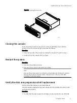
Page 32: ... up sequence After you finish Remove and store the ESD gear Installing and locking the front bezel Refer to Figure 9 on page 33 while performing the procedure that follows Procedure 1 Align the bezel with the enclosure 2 Gently push the bezel into place until it latches 3 Secure the bezel by turning the key in the lock Disk Replacement for a DAE Shelf 32 EMC CloudBoost 100 2 0 Hardware Component R...

Page 33: ...e and is noted as failed when first installed An auto spare process should change the status to OK in a few minutes Procedure 1 At the CLI for the CloudBoost appliance type support system report then after the system report is displayed type disk The state of all disk drives is displayed Note the status line in the command output Enter the data item to view details or press ENTER to return System ...

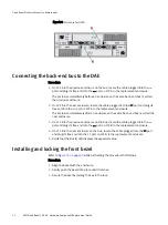
Page 34: ...nsed 0 fault_reqstd 0 device_off 0 ei 0 ti 0 capacity 3 00 TB serial P9GZS0JW temperature 32 C temp_threshold 85 slot_id 1 Disk Replacement for a DAE Shelf 34 EMC CloudBoost 100 2 0 Hardware Component Replacement Guide ...

Page 35: ...the front bezel 38 l Removing a DAE from the cabinet 40 l Unpacking a part 41 l Installing an empty DAE on the rails 42 l Transferring components from the faulted DAE to the replacement DAE 44 l Connecting powers to the replacement enclosure 50 l Verifying DAE status 51 l Connecting the back end bus to the DAE 52 l Installing and locking the front bezel 52 l Closing the console 53 l Restart the sy...

Page 36: ... wait for state stop waiting Stopping IPMI event daemon OK Disconnecting a DAE from the back end bus Procedure 1 On LCC A in the faulted enclosure Figure 10 on page 36 a Unplug the SAS cable from the port b Unplug the SAS cable from the port 2 On LCC B in the faulted enclosure Figure 10 on page 36 a Unplug the SAS cable from the port b Unplug the SAS cable from the port Figure 10 Unplugging a SAS ...

Page 37: ...nsole is a protruding plastic banner on the front of the cabinet with a stripe of blue or green light and the product badge If the console is covering the front of the to which you need access open the console using the steps that follow Procedure 1 Grasp the right side of the console 2 Pull the console to swing it open CloudBoost Disk Array Expansion Replacement Disconnecting DAE power cords 37 ...

Page 38: ...when the enclosure is powered up Remove it only to replace or add a disk Procedure 1 Insert the key that shipped with your enclosure into the bezel lock and turn it to release the lock 2 Press the two latch buttons on the bezel surface to release the bezel from the cabinet Figure 13 on page 39 CloudBoost Disk Array Expansion Replacement 38 EMC CloudBoost 100 2 0 Hardware Component Replacement Guid...

Page 39: ...ont bezel CL4560 3 Pull the bezel off and put it on a clean static free surface Figure 14 on page 39 Figure 14 Removing the front bezel CL4561 CloudBoost Disk Array Expansion Replacement Unlocking and removing the front bezel 39 ...

Page 40: ...er der Beschädigung des Gerätes bitte das Gehäuse nicht ohne die Hilfe einer zweiten Person anheben und einbauen Il contenitore è pesante e dev essere installato nel rack da due persone Per evitare danni personali e o all apparecchiatura non tentare di sollevare ed installare in un rack il contenitore senza un sollevatore meccanico e o l aiuto di un altra persona Debido a su considerable peso la i...

Page 41: ...net and place it on a static free work surface Figure 16 on page 41 Figure 16 Sliding the enclosure out of the cabinet CL4718 Unpacking a part Procedure 1 Wear ESD gloves or attach an ESD wristband to your wrist and the enclosure in which you are installing the part 2 Unpack the part and place it on a static free surface CloudBoost Disk Array Expansion Replacement Unpacking a part 41 ...

Page 42: ...he enclosure slides into the back of the cabinet the rear tabs on each rail insert into the two notches in the rear of the enclosure The tabs secure and support the rear of the enclosure Figure 18 on page 43 If the enclosure does does not slide all the way into the cabinet you may need to further loosen the screws that hold the rear of the rails in place and then adjust the rails to allow the tabs...

Page 43: ...e rails to the channels 3 Secure the front of the enclosure to the front vertical channels of the cabinet using four screws two per side by installing all four screws and then tightening them Figure 19 on page 43 Figure 19 Securing enclosure to the front of the cabinet Screw 2 Screw 2 CL4730 CloudBoost Disk Array Expansion Replacement Installing an empty DAE on the rails 43 ...

Page 44: ... of the faulted DAE to position A of the replacement DAE n Move components from position B of the faulted DAE to position B of the replacement DAE l Transfer each disk and disk filler module to the SAME SLOT LOCATION that it occupied in faulted DAE Removing a power cooling module Refer Figure 20 on page 44 to while performing the procedure that followins Procedure 1 Turn the captive screw counterc...

Page 45: ...dule shown CL4569 Removing an LCC Refer to Figure 22 on page 46 while performing the procedure that follows Procedure 1 Attach an ESD wristband to your wrist and the enclosure in which you are replacing the LCC 2 Turn the captive screws counterclockwise to release the LCC 3 Remove the LCC from its slot and place it on a clean static free surface CloudBoost Disk Array Expansion Replacement Removing...

Page 46: ...cedure 1 Attach an ESD wristband to your wrist and the enclosure 2 Gently insert the LCC being sure the LCC is completely seated in the enclosure 3 Secure the LCC with the captive screws Figure 23 Installing an LCC CL4573 CloudBoost Disk Array Expansion Replacement 46 EMC CloudBoost 100 2 0 Hardware Component Replacement Guide ...

Page 47: ...n data unavailability and possible data loss Removing a disk Refer to Figure 24 on page 47 while performing the procedure that follows Procedure 1 Pull the latch on the disk up 2 Slowly pull the disks from its slot 3 Place the disk on a static free surface Figure 24 Removing a disk CL4563 2 3 1 Installing a new or replacement disk Before you begin Use ESD gloves or attach an ESD wristband to your ...

Page 48: ...downward when its tabs meet the enclosure 4 After the latch is engaged push firmly on the bottom of the disk to verify that the disk is properly seated Figure 25 Installing a disk 1 2 Tabs CL4645 4 3 The disk s active light flashes to reflect the disk s spin up sequence After you finish Remove and store the ESD gear Removing a disk filler module Refer to Figure 26 on page 49 while performing the p...

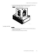
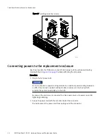
Page 49: ...ot Figure 26 Removing a disk filler module 1 2 CL5283 Installing a disk filler Procedure 1 Hold the disk filler with you thumb in the cutout on the front of the filler and your finger on the top of the filler 2 Push the disk filler module all the way into the slot CloudBoost Disk Array Expansion Replacement Transferring disks and disk filler modules 49 ...

Page 50: ...ower cooling module in an optional power cooling module to an SPS Only connect a power cooling module in enclosure 0 on bus 0 which contains the system vault disks to the SPS As soon as the enclosure is connected to a live power source it powers up and its lights begin blinking 2 Secure the power cord with the retention bail at the connector The bail prevents the power cord from pulling out of the...

Page 51: ...cedure 1 Verify that the DAE power LED is lit and that the power fault and blower fault LEDs are not lit Figure 29 on page 51 Figure 29 Enclosure status LEDs 2 Verify that the DAE fault LED is not lit Figure 30 on page 52 CloudBoost Disk Array Expansion Replacement Verifying DAE status 51 ...

Page 52: ...lled the next enclosure 3 On LCC B in the previous enclosure on the bus locate the cable plugged into the port and plug its free end into the port on LCC B in the replacement enclosure 4 On LCC B in the next enclosure on the bus locate the cable plugged into the port and plug its free end into the port on LCC B in the replacement enclosure 5 Verify that the Bus ID LED displays the expected value I...

Page 53: ...econnect the AC power cords and the wire bales Note Because the system powers on and boots automatically when AC power is restored this must be the last connection made If the system won t boot contact EMC CloudBoost Technical Support Verify the disk array expansion shelf replacement Verify that the DAE shelf was successfully replaced This task involves verifying that the power supply the link con...

Page 54: ...90007000 0 Select a device 1 3 or 0 to quit 4 In the output ensure these MPT ports are found ioc0 ioc1 and ioc2 If only one is found the system does not contain or recognize the replacement expansion module 5 Select devices 1 and 2 in turn and review their SAS SLIC information If the SLIC value for Board Name is Falcon it is the internal module If the SLIC value for Board Name Coldfront it is an e...

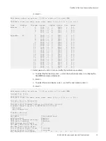
Page 55: ... all links are enabled a To select the first device enter 1 and at the next prompt enter 68 to display the SAS WWID and associated ports b Enter 0 c To select the second device enter 2 and at the next prompt enter 68 d Enter 0 Main menu select an option 1 99 or e p w or 0 to quit 68 Current Port State SAS2008 s links are down down down down 6 0 G 6 0 G 6 0 G 6 0 G Software Version Information Curr...

Page 56: ...cca058387afd 13 0 5 0 Disk HITACHI HUS72403CLAR3000 C250 5000cca05837db59 14 0 6 0 Disk HITACHI HUS72403CLAR3000 C250 5000cca05837dc35 15 0 7 0 Disk HITACHI HUS72403CLAR3000 C250 5000cca05837dcb5 16 0 8 0 Disk HITACHI HUS72403CLAR3000 C250 5000cca058344bf9 17 0 9 0 Disk HITACHI HUS72403CLAR3000 C250 5000cca05837535d 18 0 10 0 Disk HITACHI HUS72403CLAR3000 C250 5000cca05837874d 19 0 11 0 Disk HITAC...

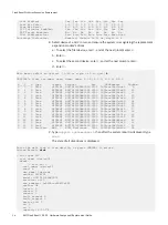
Page 57: ...5000604800a0ef03f attached SAS address 0x500604800a0ef03f attached phy identifier 9 Invalid DWORD count 2 Running disparity error count 2 Loss of DWORD sychronization 5 Phy reset problem 0 Phy event descriptors Invalid word count 2 Running disparity error count 2 Loss of dword synchronization count 5 Phy reset problem count 0 11 In the output verify that either sas_address displayed matches the sa...

Page 58: ...capacity 3 00 TB serial P9GZS0JW temperature 32 C temp_threshold 85 slot_id 1 CloudBoost Disk Array Expansion Replacement 58 EMC CloudBoost 100 2 0 Hardware Component Replacement Guide ...

Reviews: