168, 168H, and 68 Series
2
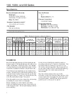
Specifications
maximum allowable pressures
Diaphragm
168 Series:
100 psi (6,90 bar)
168H Series:
150 psi (10,3 bar)
body:
See Table 1
operative Temperature limits
(1)
-10° to 150°F (-23° to 66°C)
port Diameter
3/32-inch (2,38 mm)
Flow Coefficients
c
g
:
7
representative c
1
:
35
pressure connections
1/4-inch NPT female
approximate Weights
68 Series:
0.5 pound (0,23 kg)
168 Series:
3 pounds (1,36 kg)
168H Series:
5 pounds (2,27 kg)
1. This term is defined in ISA Standard S51.1-1979.
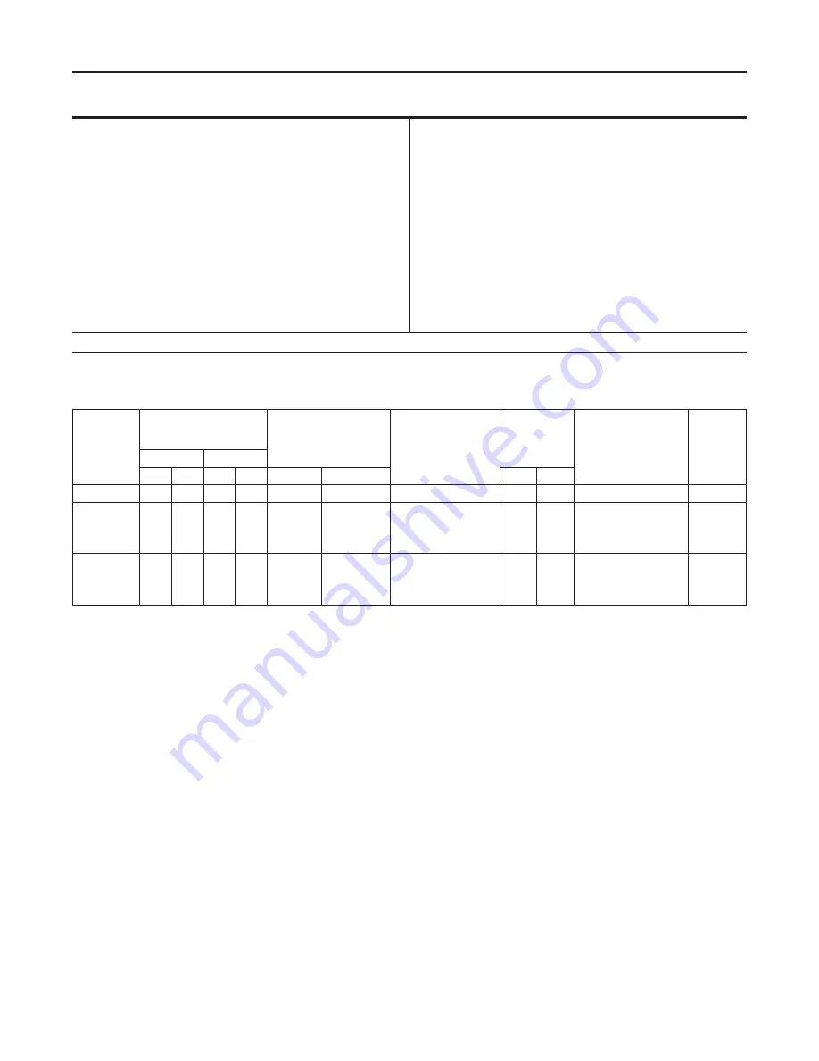
Table 1.
Maximum Pressures and Spring Part Numbers
compleTe
SWITcHIng
ValVe Type
number
DIapHragm preSSure
cHange beTWeen
SWITcHIng poInTS
DIapHragm
preSSure range
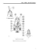
key 8, fIgure 3
DIapHragm SprIng
parT number anD
color coDe
maxImum
alloWable
boDy
preSSure
key 2D, fIgure 4
boDy SprIng parT
number anD
color coDe
boDy
aSSembly
Type
number
minimum
maximum
psi
bar
psi
bar
psi
bar
psi
bar
- - - -
- - - - - - - - - - - - - - - -
- - - -
- - - -
- - - -
150
10,3
1U878037022, Metallic
68-2
168-1
168-2
168-3
168-4
10
10
10
7
0,69
0,69
0,69
0,48
58
38
58
38
4,00
2,62
4,00
2,62
2 to 60
2 to 40
2 to 60
2 to 40
0,14 to 4,14
0,14 to 2,76
0,14 to 4,14
0,14 to 2,76
1U877127142, green
1U879727142, yellow
1U877127142, green
1U879727142, yellow
150
150
40
40
10,3
10,3
2,76
2,76
1U878037022, Metallic
1U878037022, Metallic
1U854537022, Yellow
1U854537022, Yellow
68-1
68-1
68-3
68-3
168H-1
168H-2
168H-3
168H-4
20
20
20
16
1,38
1,38
1,38
1,10
100
65
100
65
6,90
4,48
6,90
4,48
50 to 150
35 to 100
50 to 150
35 to 100
3,45 to 10,3
2,41 to 6,90
3,45 to 10,3
2,41 to 6,90
1U877127142, green
1U879727142, yellow
1U877127142, green
1U879724142, yellow
150
150
40
40
10,3
10,3
2,76
2,76
1U878037022, Metallic
1U878037022, Metallic
1U854537022, Yellow
1U854537022, Yellow
68-1
68-1
68-3
68-3
Installation
Maximum allowable pressures for the diaphragm and
body are given in the Specifications section above and
Table 1 respectively. If pressure to the unit is capable
of exceeding these values, install relief valves or other
overpressure protection devices in the pressure lines.
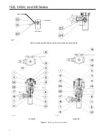
The 68 Series body assemblies can be installed in any
position. Position a 168 or 168H Series switching valve
so that moisture and other foreign material cannot enter
either the vent (key 17, Figure 3) or the small hole in the
end of the stem protector (key 10, Figure 3).
When the switch is in service, inspect the vent opening
periodically to ensure that it is not plugged.
Before installing, be certain that the valve body
portion and adjacent pipes are free of pipe scale and
other foreign material. Use accepted piping practices
when installing.
For the 168 and 168H Series switching valves, a
mounting bracket (key 15, Figure 3) is available. This
mounting bracket is suitable for use with a 2-inch
(50,8 mm) (nominal) pipestand. Mounting parts that
can be used to attach a 168 or 168H Series switching
valve to the yoke of a control valve actuator are
also available.
Pipe the common pressure line to port A (the
connection in the end of the valve body portion). With
one port (either B or C) plugged, the unit can be used
as an on/off switch. Note that flow cannot pass from
port B to port C or from port C to port B.


