
168, 168H, and 68 Series
3
168 and 168H Series adjustment
Determine the desired upper and lower switching
pressures (the high and low values of diaphragm
pressure at which the valve is to switch). Refer to
Table 1 to ensure that these pressures are within the
diaphragm pressure range and that the diaphragm
pressure change between the switching pressures is
within the minimum and maximum limits shown.
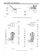
Adjust the unit as follows. Key numbers used in this
procedure are shown in Figure 3 except where indicated.
1. Remove screws and stem protector (keys 11
and 10).
2. To set the lower switching pressure:
2.1 Apply a pressure to the diaphragm case (key 1)
equal to the lower switching point.
2.2 Loosen locknut (key 9). Use a screwdriver
to move the trip lever (key 2C) so that the
visible end points away from the spring case
(key 2A). It might be necessary to back the
adjusting nut (key 7) and locknut away from
the trip lever to do this.
2.3 Rotate the adjusting nut toward the trip lever
until the nut just moves the trip lever to the
alternate position.
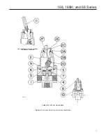
3. To set the upper switching pressure:
3.1 Apply a pressure to the diaphragm case (key 1)
equal to the upper switching pint.
3.2 Loosen the locknut on the upper range
adjusting nut. Use a screwdriver to move
the trip lever (key 2C) so that its visible
end points toward the spring case (key 2A).
It may be necessary to back the adjusting
nut and locknut away from the trip lever to
do this.
3.3 Rotate the upper range adjusting nut toward
the trip lever until the nut just moves the trip
lever to its alternate position.
4. Tighten each locknut against its respective
adjusting nut.
5. Replace stem protector and machine screws
(key 11).
168 and 168H Series manual
reset operation
Without manual reset Switch
With one adjusting nut removed, the unit will switch
with high (or low) diaphragm pressure and will remain in
that position until the stem protector (key 10, Figure 3) is
removed and the trip lever (key 2C, Figure 4) is manually
moved to its normal position. Remove the range
adjusting nut (and its locknut) located nearer the spring
case (key 2A, Figure 3) if switching at low diaphragm
pressure only is desired. Remove the other adjusting
nut and locknut if switching with high diaphragm
pressure only is desired. The remaining adjusting nut
can be adjusted by the appropriate steps given in the
Adjustment section.
To reset the unit after it has switched, remove the
machine screws and stem protector (keys 11 and 10,
Figure 3), and use a screwdriver to return the trip lever
(key 2C, Figure 4) to its normal position.
With manual reset Switch
When a manual reset switch (see Figure 3) is used
on a unit in the single-pressure trip mode (either high
or low pressure setpoint requiring only one adjusting
nut), the end of the reset lever (key 20) in contact
with the trip lever (see section DD, Figure 3) should
be on the opposite side of the trip lever from the
adjusting nut.
If it is necessary to change the reset lever position,
remove the self tapping screws (key 23). Slide the lever
out of the stem protector slots, and position it on the
other side of the trip lever and re-insert. Re-attach the
indicator tag with the self-tapping screws, making sure
the arrow on the tag points in the same direction as
that required to reset the switch.


