40
Series 7400 Single Phase 1+N UPS
4.3 Output Interface (Remote Alarms) Board (100215120007 & 100215120002)
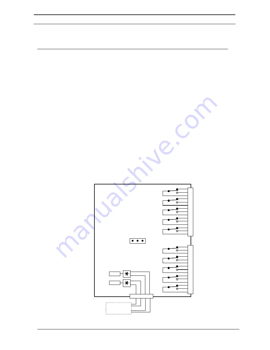
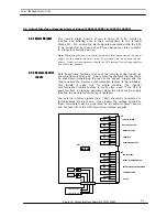
Two remote alarm boards, shown in figure 23 & 24, similar in
function and differing only in their connections to the terminal
blocks M1 - M3, enable the alarm signals generated within the UPS
to be connected by means of volt-free changeover relay contacts
to a remote monitoring device.
Note:
When using the above contacts for remote alarm annunciation, the power
supply for the remote indicators must be provided from an external power
source. Under no circumstances should the UPS internal low voltage supplies
be used for this purpose.
Both board have facilities to accept two remote control inputs, as
shown in figures 23 and 24. One remote input allows the inverter to
be shut down (transferring the load to the bypass supply) and the
other enables the inverter synchronisation feature to be inhibited.
This facility is valid only for single module. The inverter
synchronisation inhibit feature is most often used if the UPS is
powered from a standby generator when the input mains supply
fails and the generator frequency is unstable.
The external control signals (12V / 24V) should be connected to
terminal block M2 as shown. Once again, the voltage applied to
these terminals must be generated by an external power source
and not taken from the UPS internal low voltage supplies.
4.3.1 Alarm Outputs
4.3.2 Remote Control
Inputs
15
14
13
12
11
10
9
8
7
6
5
4
3
2
1
15
14
13
12
11
10
9
8
7
6
5
4
3
2
1
LOAD ON BYASS
BATTERY ON LOAD
MAINS FAILURE
OVERLOAD
OVER TEMPERATURE
M2
M3
LOW BATTERY
MAINT. BYPASS ENABLED
INVERTER UNSYNCHRONISED
COMMON ALARM
UPS OK
1 2 3
SH1
RELAY
RELAY
M1
SYNCHRO INHIBIT
INVERTER ON/OFF
1 2 3 4 5
Figure 23: Output Interface Board #100215120007


