background image

Quick Start Guide

00825 0100-4421, Rev DC

September 2020

Emerson Wireless Field Link

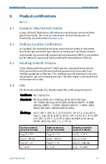
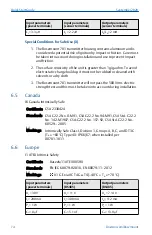
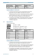
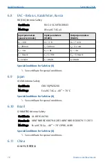
Summary of Contents for 781

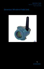
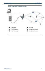
Page 1: ...Quick Start Guide 00825 0100 4421 Rev DC September 2020 Emerson Wireless Field Link ...

Page 2: ...oduct Certifications section for any restrictions associated with a safe installation Electrical shock could cause death or serious injury Avoid contact with the leads and terminals High voltage that may be present on leads can cause electrical shock This device complies with Part 15 of the FCC Rules Operation is subject to the following conditions This device may not cause harmful interference Th...

Page 3: ... that allows convenient access to the host system network wireless I O as well as the wireless field device network Find a location where the Field Link has optimal wireless performance Ideally this will be 15 to 25 ft 4 6 to 7 6 m above the ground or 6 ft 2 m above obstructions or major infrastructure Figure 1 1 Mounting Location A B C D E 15 to 25 ft 4 6 to 7 6 m 6 ft 2 m A Control room B Ground...

Page 4: ...ced with the included conduit plugs using approved thread sealant Figure 1 3 Conduit Plugs A A A Conduit plug 1 5 Intended use The Field Link must be used in conjunction with a network manager or network Gateway The Field Link then functions as a translator between the wired network and a wireless field network Quick Start Guide September 2020 4 Emerson com Rosemount ...

Page 5: ...1 4 Example System Architecture A B C D E F A Host system B Control network C Network manager D Field link E Wireless field network F Wireless field devices September 2020 Quick Start Guide Quick Start Guide 5 ...

Page 6: ...gh the L shaped bracket 4 Use a 1 2 in socket head wrench to fasten the nuts to the U bolt Figure 2 1 Mounting 2 2 Power and data wiring Procedure 1 Remove housing cover labeled Field Terminals 2 Connect the positive power lead to the power terminal and the negative power lead to the terminal 3 Connect the Data lead to the A terminal and the Data lead to the B terminal 4 Plug and seal any unused c...

Page 7: ...e should always be grounded in accordance with national and local electrical codes The most effective grounding method is a direct connection to earth ground with minimal impedance Ground the Field Link by connecting the external ground lug to earth ground The connection should be 1 Ω or less September 2020 Quick Start Guide Quick Start Guide 7 ...

Page 8: ...Tag 4 Startup Screen 4 Status 3 2 Normal operation After the initial startup screens the Field Link will cycle through several periodic screens 1 Electronics Temperature Screen 2 Percent Range Screen 3 Wired Interface Usage 4 Radio Interface Usage The Field Link will continue to rotate through each periodic screen through the course of normal operation If any diagnostic or fault condition occurs a...

Page 9: ...ireless Field Link Terminal Diagram A B C D A Data A B Data B C 10 5 to 30 VDC D Return Note The Emerson Wireless Field Link requires separate twisted shield pairs four wires for power and data September 2020 Quick Start Guide Quick Start Guide 9 ...

Page 10: ...40 to 185 F 40 to 85 C Wiring power 24 AWG 14 AWG twisted shielded pair 1 Wiring RS 485 communications 24 AWG 14 AWG twisted shielded pair 1 Less than 15 pF ft capacitance Wiring distance 656 ft 200 m Wireless protocol WirelessHART 2 4 2 5 GHz DSSS Wireless output power EIRP 10 dBm with WK antenna and 12 5 dBm with WM antenna Mounting All SST 2 in pipe and panel mount bracket Humidity 0 90 relativ...

Page 11: ... certifications I5 USA Intrinsically Safe Non incendive I6 Canada Intrinsically Safe I1 ATEX Intrinsic Safety I7 IECEx Intrinsic Safety KD USA and Canada Intrinsically Safe ATEX and IECEx Intrinsic Safety I2 INMETRO Intrinsic Safety I4 Japan Intrinsic Safety IM EAC Intrinsic Safety I3 China NEPSI Intrinsic Safety KL USA and Canada Intrinsic Safety ATEX Intrinsic Safety NA No Approvals Wireless upd...

Page 12: ...tions Include with selected model number Meter M5 LCD display Gland and connector options G2 Cable gland 7 5 11 9 mm G4 Thin wire cable gland 3 8 mm Typical model number 781 A1 D 1 KL WA3 WK3 M5 Quick Start Guide September 2020 12 Emerson com Rosemount ...

Page 13: ...ions The markings must be suitable for the area classification gas and temperature class This information is clearly defined in the respective codes 6 4 USA I5 USA Intrinsically Safe IS Nonincendive NI and Dust ignitionproof Certificate FM 17US0235X Standards FM Class 3600 2011 FM Class 3610 2010 FM Class 3611 2004 FM Class 3810 2005 ANSI ISA 60079 0 2009 ANSI UL 60079 11 2009 ANSI ISA 61010 1 200...

Page 14: ... Vrms electric strength test and this must be taken into account during installation 6 5 Canada I6 Canada Intrinsically Safe Certificate CSA 2330424 Standards CSA C22 2 No 0 M91 CSA C22 2 No 94 M91 CSA Std C22 2 No 142 M1987 CSA C22 2 No 157 92 CSA Std C22 2 No 60529 2005 Markings Intrinsically Safe Class I Division 1 Groups A B C and D T3C Ta 60 C Type 4X IP 66 67 when installed per 00781 1011 6 ...

Page 15: ...Ex BAS 11 0028X Standards IEC 60079 0 2011 IEC 60079 11 2011 Markings Ex ia IIC T4 Ga T4 40 C Ta 70 C Input parameters power terminals Input parameters RS485 Output parameters RS485 Ui 30 V Ui 11 V Uo 7 14 V Ii 200 mA Ii 300 mA Io 112 mA Pi 1 W Pi 1 W Po 1 W Ci 0 μF Ci 5 1 nF Co 13 9 μF Li 0 mH Li 0 mH Lo 1000 μH Special Conditions for Safe Use X 1 The plastic antenna may present a potential elect...

Page 16: ... for Safe Use X 1 See certificate for special conditions 6 9 Japan I4 CML Intrinsic Safety Certificate CML 18JPN2024X Markings Ex ia IIC T4 Ga 40 70 C Special Conditions for Safe Use X 1 See certificate for special conditions 6 10 Brazil I2 INMETRO Intrinsic Safety Certificate UL BR 16 0478X Standards ABNT NBR IEC 60079 0 2013 ABNT NBR IEC 60079 11 2013 Markings Ex ia IIC T4 Ga 40 70 C IP66 UL BR ...

Page 17: ... 0 RS485 11 300 1 5 1 0 输出 最高输出 电压 Uo V 最大输出 电流 Io mA 最大输出 功率 Po W 最大外部等效参数 Co µF Lo µH RS485 7 14 112 1 13 9 0 3 该产品必须与已通过防爆认证的关联设备配套共同组成本安防爆系 统方可使用于爆炸性气体环境 其系统接线必须同时遵守本产品和 所配关联设备的使用说明书要求 接线端子不得接错 4 用户不得自行更换该产品的零部件 应会同产品制造商共同解决运 行中出现的故障 以杜绝损坏现象的发生 5 产品的安装 使用和维护应同时遵守产品使用说明书 GB3836 13 2013 爆炸性环境 第 13 部分 设备的修理 检修 修 复和改造 GB T3836 15 2017 爆炸性环境 第 15 部分 电气装置 的设计 选型和安装 GB T3836 16 2017 爆炸性环境 第 16 部 分 电气...

Page 18: ...6 12 Combinations KD Combination of I1 I5 and I6 KL Combination of I1 I5 I6 and I7 Quick Start Guide September 2020 18 Emerson com Rosemount ...

Page 19: ...Figure 6 1 Rosemount 781 Declaration of Conformity September 2020 Quick Start Guide Quick Start Guide 19 ...

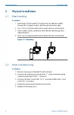
Page 20: ...Quick Start Guide September 2020 20 Emerson com Rosemount ...

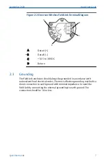
Page 21: ...September 2020 Quick Start Guide Quick Start Guide 21 ...

Page 22: ... X O O X O O ᵜ㺘Ṭ ᦞ SJ T11364Ⲵ㿴ᇊ㘼ࡦ This table is proposed in accordance with the provision of SJ T11364 O Ѫ䈕䜘ԦⲴᡰᴹ 䍘ᶀᯉѝ䈕ᴹᇣ 䍘Ⲵਜ਼䟿 վҾGB T 26572ᡰ㿴ᇊⲴ䲀䟿㾱 O Indicate that said hazardous substance in all of the homogeneous materials for this part is below the limit requirement of GB T 26572 X Ѫ 䈕䜘Ԧᡰ Ⲵᡰᴹ 䍘ᶀᯉ䟼ˈ㠣ቁᴹа 䍘ᶀᯉѝ䈕ᴹᇣ 䍘Ⲵਜ਼䟿儈ҾGB T 26572ᡰ㿴ᇊⲴ䲀䟿㾱 X Indicate that said hazardous substance contained in at least ...

Page 23: ...September 2020 Quick Start Guide Quick Start Guide 23 ...

Page 24: ...H 6340 Baar Switzerland 41 0 41 768 6111 41 0 41 768 6300 RFQ RMD RCC Emerson com Asia Pacific Regional Office Emerson Automation Solutions 1 Pandan Crescent Singapore 128461 65 6777 8211 65 6777 0947 Enquiries AP Emerson com Middle East and Africa Regional Office Emerson Automation Solutions Emerson FZE P O Box 17033 Jebel Ali Free Zone South 2 Dubai United Arab Emirates 971 4 8118100 971 4 88654...

Reviews: