24
| 2.0
installation
4.
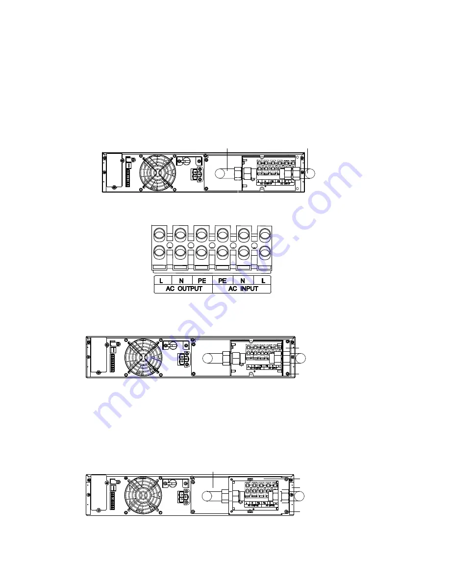
Connect the input power source line, neutral, and ground cables to the input line (L), neutral (n), and ground (PE)
terminals on the UPS i/O terminal block and tighten the fixing screws (see Figures 18 and 19).
5.
Connect the UPS output line, neutral and ground cables to the output line (L), neutral (n), and ground (PE) terminals
on the UPS i/O terminal block and tighten the fixing screws (see Figures 18 and 19).
Output cable
Input cable
Figure 18: I/O Cable placement
Figure 19: UPS I/O terminal block
6.
Use two rear panel mounting screws to install Base 2 to the UPS rear panel, as shown in Figure 20.
Base 2
Screw (2 pcs)
Figure 20: Installing Base 2
7.
insert the input and output cables/hardware into the slots on Base 2 and Base 1. Hand tighten the securing nuts to
Base 2 and Base 1.
8.
Set the box onto the Base 1 and Base 2 cable/hardware assemblies. Use the four box assembly screws to fasten the
box to the bases (see Figure 21).
9.
Using the hardware securing nuts, tighten the input and output cable assemblies to the box and bases (see Figure 21).
Box
Screw (4 pcs)
Base 2
Base 1
Figure 21: Installing the box


