5
Model No.: ACF552
8.
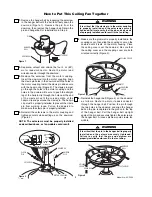
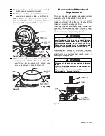
Turn fan assembly upside down in preparation for
mounting fan blade assemblies.
9.
Remove and discard the five shipping spacers and
screws from the motor hub (Figure 5).
10.
Mount a blade flange to fan blades using three
M5 x 6mm washer head blade screws (Figure 6).
Be sure the raised edge of the fan blade is facing
up. Repeat this procedure for the remaining four
blades and fan blade flanges.
NOTE: Take care not to scratch fan housing when
installing blades.
SHIPPING
SPACER (4)
SHIPPING SPACER
SCREW (4)
N
O
T
E
!
R
e
m
o
ve
R
ub
be
r P
ac
D
is
ca
rd
B
e
fo
re
In
st
al
la
tio
MOTOR HUB
Figure 5
FAN BLADE FLANGES (5)
M5 x 6mm WASHER
HEAD BLADE SCREW (3)
FAN BLADE (5)
Figure 6
To reduce the risk of personal injury, do not bend the
blade holder when installing the blade holders,
balancing the blades or cleaning the fan. Do not
insert foreign objects in between rotating fan blades.
WARNING
!
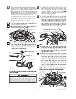
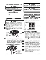
13.
Remove one M4 x 10mm serrated pan head
screw from the lower housing adapter (reserve
for later use). Loosen the other two screws to
assemble the switch cup cover to the lower
housing adapter (Figure 7).
14.
Install the switch cup cover onto the lower
housing adapter by aligning the two key holes in
the switch cup cover with the two screws
loosened in Step 13. Rotate the switch cup cover
clockwise to engage the loosened screws into the
two key hole slots. Align the third hole in the
cover with vacant threaded hole on the lower
housing adapter. Re-install the screw removed in
Step 13 into the aligned holes. Securely tighten
all three screws (figure 8).
NOTE: Make sure wires are not pinched between
switch cup cover and lower housing adapter.
BLADE ASSEMBLY
M6 x 14mm CAPTIVE
SCREW WITH
LOCKWASER
REMOVE ONE M4 x 10mm SERRATED
PAN HEAD SCREW
LOWER HOUSING
ADAPTER
Figure 7
M4 x 10mm
SERRATED PAN
HEAD SCREW (3)
ROTATE SWITCH CUP
COVER CLOCKWISE
SWITCH CUP
COVER
Figure 8
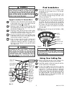
12.
The fan blade holders have an interlocking
feature that must be fully engaged before
tightening the screw. Make sure all the holders
are properly engaged and then tighten the holder
screws. If one of the fan blade holders does not
seat properly on the motor hub, loosen the
adjacent holder screws, re-engage and reseat
the holders, then tighten the screws again.
7.
The motor lead wires will require shortening if
using a 1.5 m. or shorter downrod. The fan comes
with blue, brown, orange and green/yellow motor
leads that are 2 m. (80") long. Measure up
approximately 15 cm. (6") above top of hanger
ball/downrod assembly and cut off the excess lead
wire. Strip back the wire insulation as follows:
A. Green/yellow wire - 10 mm. from the cut end.
B. Blue/brown/orange - 8 mm. from the cut end.
Twist all wire tips a minimum of 2 turns.
11.
Loosely attach one blade assembly to the motor
hub using two M6 x 14 captive pan head screws
with lockwashers installed on the fan blade
holders. Make sure the screws are NOT
tightened. (Figure 7.) Repeat this procedure for
other four blade assemblies.


