8
Model No.: ACF552
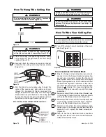
SUPPLY CABLE
TERMINAL BLOCK
(on Hanger Bracket)
BLACK WIRE
(Neutral)
RED WIRE (Active)
FROM WALL FAN
CONTROL SWITCH
BLUE WIRE
(Neutral)
N
L1
L
GREEN/YELLOW
WIRE (Earth)
FROM
HANGER
BRACKET
RED OR WHITE WIRE
(Active) FROM WALL
LIGHT SWITCH
GREEN/YELLOW
WIRE (Earth)
GREEN/YELLOW
WIRE (Earth)
FROM HANGER
BRACKET
BROWN WIRE
(Motor Active)
GREEN/YELLOW
WIRE (Earth)
FROM FAN
ORANGE WIRE
(Light Active)
GREEN/YELLOW
WIRE (Earth)
FROM HANGER
BALL
1-PIN
CONNECTORS
HANGER
BRACKET
HANGER
BALL
Figure 16
THREADED
STUDS (2)
#8 LOCKWASHER
KNURLED KNOB
CANOPY
SEAL PAD
CEILING
COVER
To avoid possible fire or shock, make sure that the
electrical wires are not pinched between the ceiling
cover and the ceiling.
WARNING
Figure 17
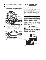
1.
Screw the two #8-32 x 1-1/4” threaded studs
(supplied) into the tapped holes in the hanger
bracket (Figure 17).
2.
Lift the ceiling cover up to the threaded studs and
turn until studs protrude through the holes in the
ceiling cover (Figure 17).
Final Installation
Using Your Ceiling Fan
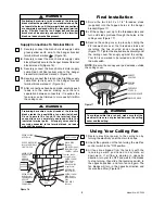
1.
Restore electrical power to the ceiling fan by
turning the electricity on at the main fuse box.
2.
Check the operation of the fan turning the wall fan
control switch to the "ON" position.
3.
All fans are shipped from the factory with the
reversing switch positioned to circulate air
downward. If airflow is desired in opposite
direction, turn your fan OFF and wait for the blades
to stop turning, then slide the reversing switch to
the opposite position, and turn fan on again. The
fan blades will turn in the opposite direction and
reverse the airflow (Figure 18).
NOTE:
Be sure the canopy seal pad extends outside
the ceiling cover.
3.
Secure the ceiling cover in place by sliding the
#8 lockwashers over the threaded studs and
installing the two knurled knobs (supplied)
(Figure 17). Tighten the knurled knobs securely until
the ceiling cover fits snugly against the ceiling.
Your fan is now wired to be turned on and off from
the wall switch.
7.
Securely connect the branch circuit supply cable
green/yellow earth wire to the hanger bracket
terminal block marked (Figure 16).
8.
Securely connect the branch circuit supply cable
black (Neutral) wire to the hanger bracket terminal
block marked N (Figure 16).
9.
Securely connect the branch circuit motor supply
cable Red or White (active) wire to the hanger
bracket terminal block marked L (Figure 16).
10.
Securely connect the branch circuit lighting supply
cable Red (active) wire to the hanger bracket
terminal block marked L1 (Figure 16).
11.
After connections have been made, carefully push
leads into the recess making sure there is
separation between connectors. If required, the
fan wires can be trimmed to more easily fit within
the ceiling cover.
Protruding bare wire or wire strands at the terminal
block creates the possibility of an electrical shock.
Do not operate the fan until the terminal block
connections are completely enclosed within the
insulated terminal ports. All supply wires shall be
securely connected to the terminal block, no loose
wire shall be present.
WARNING
Supply Connections To Terminal Block
Protruding bare wire or wire strands at the terminal
block creates the possibility of an electrical shock. Do
not operate the fan until the terminal block connections
are completely enclosed within the insulated terminal
ports. All wires from the fan, hanger ball and hanger
bracket shall be securely connected to the terminal
block, no loose wire shall be present.
WARNING


