5
Model No.: ACF765
8.
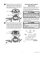
Make sure the grommet is properly installed in the
coupling cover, then slide the coupling cover on
the downrod until it rests on the motor housing.
Place the ceiling cover over the downrod. Be sure
that the ceiling cover and the coupling cover are
both oriented correctly (Figure 5).
9.
Reinstall the hanger ball (Figure 6) on the downrod
as follows. Route the two motor leads through the
hanger ball. Position the pin through the two holes
in the downrod and align the hanger ball so the pin
is captured in the groove in the top of the hanger
ball. Pull the hanger ball up tight against the pin
and securely tighten the setscrew in the hanger
ball. Loose setscrews could create fan wobble.
MOTOR COVER
CEILING COVER
DOWNROD
MOTOR COUPLING
COVER
Figure 5
CEILING COVER
PIN
HANGER
BALL
SETSCREW
DOWNROD
Figure 6
Electrical and Structural
Requirements
If your fan is to replace an existing ceiling light fixture,
turn electricity off at the main fuse box at this time and
remove the existing light fixture.
The hanger bracket must be securely anchored and
capable of withstanding a load of at least 31 Kg.
Turning off wall switch is not sufficient. To avoid
possible electrical shock, be sure electricity is turned
off at the main fuse box before wiring. All wiring must
be in accordance with National and Local codes and
the ceiling fan must be properly grounded as a
precaution against possible electrical shock.
WARNING
Disconnect electrical supply and test before you
touch!
All wiring must be in accordance with AS/NZS 3000
“The Wiring Rules”.
The warranty on this fan will be void if the appliance is
not installed by a licensed electrician.
WARNING
The ceiling fan is 230V 50Hz Class I appliance and
will require an earth. Figure 7 depicts different
structural configurations that may be used for
securely mounting the fan.
Figure 7

