Chapter 5 Operating SCU 49
ACTURA Flex 48330
Power System User Manual
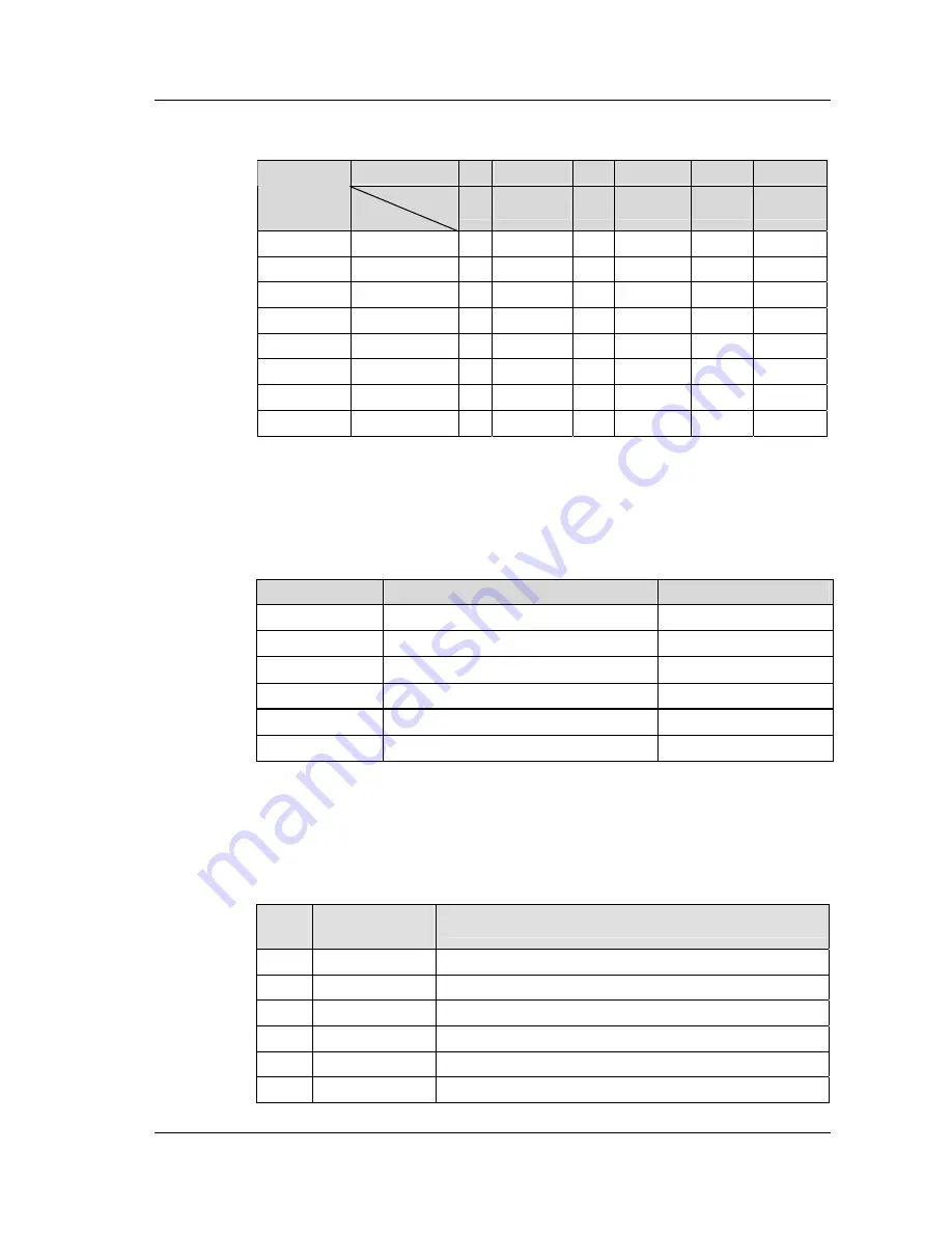
Table 5-6 Logic matrix used for configuring 8 dry contacts
Setting
0,1 Alarm SN Logic Alarm SN Logic Alarm SN
Column(B)
Row(A)
0
1
2
3
4
5
Dry Contact 0
0
Dry Contact 1
1
Dry Contact 2
2
Dry Contact 3
3
Dry Contact 4
4
Dry Contact 5
5
Dry Contact 6
6
Dry Contact 7
7
The format of PLC setting is AlarmPLC[A][B]=C.
Where, “A” is the row No., and “B” is the column No., and “C” is the value of the
matrix element. An example is shown in the following table:
Table 5-7 Example of PLC setting
PLC byte
Byte description
Function
AlarmPLC[3][0]=1
Elemant value of Row 3 and Column 0 is 1.
Use Dry Contact 3
AlarmPLC[3][1]=1
Elemant value of Row 3 and Column 1 is 1.
Alarm SN of Fuse 1 Blow up
AlarmPLC[3][2]=3
Elemant value of Row 3 and Column 2 is 3.
AND Logic
AlarmPLC[3][3]=2
Elemant value of Row 3 and Column 3 is 2.
Alarm SN of Fuse 2 Blow up
AlarmPLC[3][4]=3
Elemant value of Row 3 and Column 4 is 3.
OR Logic
AlarmPLC[3][5]=43 Elemant value of Row 3 and Column 5 is 43. Alarm SN of LLVD
For the above PLC setting: When alarms of “Fuse 1 Blow up” and “Fuse 2 Blow up”
occur at the same time, or LLVD occurs, dry contact 3 will output the alarm signal.
Relationship between PLC SN and Alarm:
Table 5-8 PLC SN and Alarm
PLC
SN
Alarm
description
Remark
0
Alarm Block
Disabled for China Market, Enabled for rest of world
1
Load 1 Failure
2
Load 2 Failure
3
Load 3 Failure
4
Load 4 Failure
5
Load 5 Failure
Summary of Contents for ACTURA Flex 48330
Page 10: ......


