background image

15

© 2012 Emerson Climate Technologies, Inc.
Printed in the U.S.A.

AE4-1287 R7

Application Engineering

B

U

L

L

E

T

I

N

 Copeland

®

 Demand Cooling

®

 Diagnostics 

Demand Cooling Operating Characteristics

The Copeland

®

 Demand Cooling

®

 control uses a 

Negative Temperature Coef

fi

 cient  Thermistor  (NTC). 

Incorporated in the Demand Cooling Temperature Sensor 

(hereafter called “sensor”), is a compressor discharge 

temperature monitor. When the temperature sensed 

by the NTC Thermistor rises, its resistance falls, and 

when temperature sensed by the thermistor drops, its 

resistance increases.


The sensor resistance signal is coupled to the Demand 

Cooling Module (hereafter called “module”). The module 

uses the signal to determine when the compressor 

discharge temperature has risen to a point where 

Demand Cooling is required. When Demand Cooling 

is required the module energizes the Demand Cooling 

Injection Valve (hereafter called “injection valve”) and 

the injection valve injects saturated refrigerant into 

the compressor suction cavity until the discharge 

temperature drops to an acceptable level.

Whenever the compressor starts and the module 

fi

 rst 

receives power, there is a one minute delay during 

which the Demand Cooling system injects saturated 

refrigerant if it is required, but waits for compressor 

discharge temperature to stabilize before checking for 

alarm conditions. After one minute, if the resistance of 

the probe is too low (the resistance equivalent of 310°F), 

or too high (the resistance equivalent of 4°F) the module 

will trip and deenergize the compressor. 

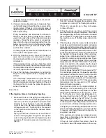
Bench Testing Demand Cooling Components 

Bench Check of the Sensor

Required Equipment:

•  A digital thermometer of +/- 1 % full scale accuracy. 

The thermometer probe should be checked for 

calibration in an ice water bath or compared with 

another accurately known temperature source.

•  A digital ohmmeter capable of +/- 1 % accuracy. The 

ohmmeter should be checked for accuracy with a 

known resistance value such as a +1 % resistor.

Room temperature should be stable and between 60°F 

and 110°F.


1. Wrap the end of the digital thermometer probe 

and the metal end of the Demand Cooling sensor 

probe together with electrical tape or “Velcro”. The 

end of the probe and the end of the thermometer 

must touch.

2. Place the wrapped probe-sensor inside an 

insulation shield to protect it from air currents. Use 

a material such as “Permagum” or piping insulation 

such as “Arma

fl

 eX”. The insulating material should 

be tightly wrapped around the taped-sensor and 

the wrap should be secured with wire or tiewraps if 

necessary. There should be no free air movement 

over the metal part of the taped-sensor. 

3.  Connect the digital ohmmeter to the two pins on 

the plug of the sensor. Make sure there is a good 

connection. Do not take a sensor resistance 

measurement until there is no change in the 

ohmmeter display.

4. Measure the temperature of the thermometer 

sensor and find the corresponding calculated 

sensor resistance value from Table 1. Since the 

values of Table 1 are not continuous, you may 

have to interpolate.

5.  The sensor resistance reading should be within 

+/- 5% of the calculated resistance value of Step 4.

End of Test

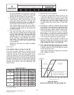
Appendix Table 1


Appendix

Thermometer 

Temp. (F°)

Calculated 

Sensor 

Resistance 

(Ohms)

59

141426

60.8

135000

62.6

128907

64.4

123129

66.2

117639

68

112437

69.8

107478

71.6

102762

73.4

98289

75.2

94041

77

90000

78.8

86139

80.6

82476

82.4

78984

84.2

75663

Thermometer 

Temp. (F°)

Calculated 

Sensor 

Resistance 

(Ohms)

86

72504

87.8

69480

89.6

66609

91.4

63864

93.2

61254

95

58770

96.8

56394

98.6

54126

100.4

51966

102.2

49914

104

47943

105.8

46053

107.6

44262

109.4

42543

Summary of Contents for AE4-1287 R7

Page 1: ...rmation 6 Demand Cooling with Discus Compressor Unloading 6 4D and 6D Unloading with Demand Cooling 6 3D Copeland Discus Digital with Demand Cooling 6 Performance Adjustment Factors 7 Demand Cooling Specifications 7 Figures and Tables Demand Cooling System 7 Low Temperature Operating Envelope with Demand Cooling for R 407A R 407C and R 407F 8 Low Temperature Operating Envelope for R 22 at 65 F Ret...

Page 2: ...hout the lifetime of the compressor You are strongly advised to follow these safety instructions Safety Icon Explanation DANGER indicates a hazardous situation which if not avoided will result in death or serious injury WARNING indicates a hazardous situation which if not avoided could result in death or serious injury CAUTION used with the safety alert symbol indicates a hazardous situation which...

Page 3: ... oils Personal safety equipment must be used Failure to follow these warnings could result in serious personal injury BURN HAZARD Do not touch the compressor until it has cooled down Ensure that materials and wiring do not touch high temperature areas of the compressor Use caution when brazing system components Personal safety equipment must be used Failure to follow these warnings could result in...

Page 4: ...rge that dangerous amounts of liquid are injected or that excessive system pressure fluctuation occurs during injection valve cycling Normally pressure fluctuations are no greater than 1 to 2 psi It is important to use the correct valve for each compressor body style Performance data for Demand Cooling compressors includes the effects of injection when it is required The approximate conditions whe...

Page 5: ...ature sensor port in the head of the compressor The locations of these ports are critical and were determined through an extensive development program The HCFC 22 HFC 407A HFC 407C and HFC 407F rating data includes the effects of Demand Cooling injection when operating conditions require it based on 65 F return gas Condenser Sizing Condensers should be sized using conventional methods Demand Cooli...

Page 6: ...oving particles as small as 25 microns 3 Do not use any filters containing materials that can leave the filter and possibly clog the IV orifice 4 The liquid refrigerant supply line must be a minimum of 3 8 and routed so it will not interfere with compressor maintenance Liquid refrigerant must have sufficient subcooling at the injection valve to prevent flashing upstream of the valve 5 The liquid r...

Page 7: ...ewhat with return gas temperature The approximate effects of return gas temperature on evaporator capacity and mass flow are tabulated in Tables 3A and 3B for HCFC 22 These factors should be applied to the 65ºF return gas capacity and mass flow values in the published performance data sheets Performance values for HFC 407A HFC 407C and HFC 407F are not provided in this bulletin For actual performa...

Page 8: ...nd Cooling would inject 90 100 110 120 130 140 emperature F 65 F Return Gas Demand Demand Cooling Required 30 40 50 60 70 80 45 40 35 30 25 20 15 10 5 0 5 Condensing Te Evapora ng Temperature F 65 F Return Gas Demand Cooling Injec on Line If Liquid Injec on Is Not Installed Recommend 265 F MAX Discharge Line Temp Limit Figure 3 Low Temperature Operating Envelope for R 22 at 65 F Return Gas with He...

Page 9: ...ONTROL CIRCUIT REFRIGERANT INJECTION LINE MANUAL SHUTOFF VALVE INJECTION LINE FILTER DEMAND COOLING SENSOR AND SENSOR LINES RECEIVER LIQUID LINE FILTER DRIER COMPRESSOR EVAPORATOR INJECTION SOLENOID VALVE SIGHT GLASS SUCTION LINE FILTER ACCUMULATOR CONDENSER M L A S TXV INJECTION VALVE ELECTRICAL CONTROL LINE Figure 4 Demand Cooling System Diagram ...

Page 10: ...mpressor Motor Demand Cooling Module Sentronic Control Temp Sensor Electronic Switch Injection Solenoid L1 L2 L3 L1 L2 L M A S CC CS NOTE The control circuit must be arranged so that the Demand Cooling Module and the Sentronic are deenergized when the compressor is not running 240vac Current Sensing CS Relay Compressor Contactor CC Compressor Motor Demand Cooling Module Controls Temp Sensor Electr...

Page 11: ...nd Cooling Module Sentronic Controls Temp Sensor Electronic Switch Injection Solenoid L1 L2 L M S A L M A 240 2 L1 L2 NOTE The control circuit must be arranged so that the Demand Cooling Module and the Sentronic are deenergized when the compressor is not running Demand Cooling Module Controls Temp Sensor Electronic Switch Injection Solenoid Sentronic Oil Pressure Control Figure 5C Demand Cooling W...

Page 12: ... Injection Solenoid Temp Sensor Injector Control Switch L M A S Demand Cooling Module CoreSense Module Terminal Strip 120v or 240v NOTE The CoreSense module is dual rated for 120v 240v The Demand Cooling module must be matched to the line voltage Current Sensor Current Sensor Connector Contactor Figure 5E Coresense Protection with Copeland Demand Cooling ...

Page 13: ...1 26 60HZ 120V 998 1000 12 998 1000 13 998 1000 14 998 1000 16 998 2000 14 998 2000 16 240V 998 1000 22 998 1000 23 998 1000 24 998 1000 26 998 2000 24 998 2000 26 Demand Cooling Kits Include Demand Cooling Module with 2 Mounting Screws Temperature Sensor with 3ft Shielded cable Injection Valve and Solenoid without mounting hardware Installation Troubleshooting Guide Optional Demand Cooling Module...

Page 14: ...rson Climate Technologies Inc and or its affiliates collectively Emerson as applicable reserve the right to modify the design or specifications of such products at any time without notice Emerson does not assume responsibility for the selection use or maintenance of any product Responsibility for proper selection use and maintenance of any Emerson product remains solely with the purchaser or end u...

Page 15: ... probe should be checked for calibration in an ice water bath or compared with another accurately known temperature source Adigital ohmmeter capable of 1 accuracy The ohmmeter should be checked for accuracy with a known resistance value such as a 1 resistor Room temperature should be stable and between 60 F and 110 F 1 Wrap the end of the digital thermometer probe and the metal end of the Demand C...

Page 16: ...g and loosen its housing cover screw until magnet vibration is felt This proves solenoid operation Retighten the magnet housing cover screw after this check 6 After one minute the module should trip The run contact L to M shouldopen andthealarmcontact L to A should close Deenergize the module and disconnecttheinjectionvalve Theresistanceshould be zero ohms between L and A and between L and M there...

Page 17: ...rises then go to Step 6 2 Deenergize the system and disconnect the sensor from the module Energize the system so the compressor is running The frosting should stop If Step 2 is successful go to Step 4 otherwise continue to Step 3 3 If frosting does not stop with the sensor disconnected deenergize the system Disconnect the voltage supply to the injection valve and restart the compressor If frosting...

Page 18: ...r injection to start The result of this cycling is that frost on the injection valve outlet tubing alternately appears during injection and then disappears after injection stops 1 Measure the room temperature 2 Connect the temperature sensor probe to the compressor discharge line 6 from the discharge valve The probe must be tightly secured to the discharge line and must be well insulated so that m...

Reviews: