background image

1


© 2018 Emerson Climate Technologies, Inc.


AE8-1384 R6 

March 2018


CoreSense™ Communications for 20 to 40 Ton 

Copeland Scroll™ Air Conditioning Compressors


TABLE OF CONTENTS


Section 

Page


Safety


Safety Instructions. ...................................................... 2


Safety Icon Explanation. .............................................. 2


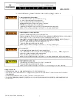
Instructions Pertaining to Risk of Electrical


Shock, Fire, or Injury to Persons .................................. 3


Safety Statements. ...................................................... 3


Introduction


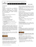
Overview ...................................................................... 4


Features ...................................................................... 4


Application Usage ....................................................... 4


Part Numbers .............................................................. 4


Agency Recognition .................................................... 4


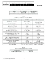
Product Specifications ................................................. 4


Installation


Mounting ...................................................................... 4


Terminal Description and Basic Field Wiring. .............. 4


Dielectric (Hipot) Testing .................................................. 5


Operation


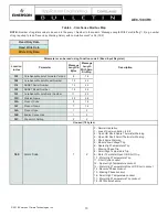
Warning Codes ............................................................ 5


Alert/Lockout Codes .................................................... 5


Resetting Alert Codes ................................................. 6


Section 

Page


Commissioning


Communications .......................................................... 6


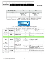
DIP Switch Configuration ............................................ 7


Jumper Setting. ........................................................... 7


PC Interface Software. ................................................. 7


Service


Field Service ................................................................ 8


Troubleshooting ........................................................... 8


Tables


Module Part Numbers .................................................. 9


Module Specifications ................................................. 9


Accessory Parts .......................................................... 9


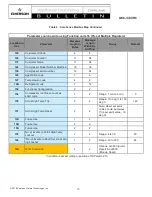
Modbus Map ......................................................... 10-12


DIP Switch Purpose ................................................... 13


LED Flash Code Information ................................ 13-14


Figures


Terminal Box Wiring Diagrams ................................... 15


CoreSense

™ Communications Module Photo. ......... 16


Thermistor Circuit Cable ............................................ 16


Modbus Addressing ................................................... 17


Summary of Contents for AE8-1384 R6

Page 1: ...ion 4 Product Specifications 4 Installation Mounting 4 Terminal Description and Basic Field Wiring 4 Dielectric Hipot Testing 5 Operation Warning Codes 5 Alert Lockout Codes 5 Resetting Alert Codes 6 Section Page Commissioning Communications 6 DIP Switch Configuration 7 Jumper Setting 7 PC Interface Software 7 Service Field Service 8 Troubleshooting 8 Tables Module Part Numbers 9 Module Specificat...

Page 2: ...etained throughout the lifetime of the compressor You are strongly advised to follow these safety instructions Safety Icon Explanation DANGER indicates a hazardous situation which if not avoided will result in death or WARNING indicates a hazardous situation which if not avoided could result in death or serious injury CAUTION used with the safety alert symbol indicates a hazardous situation which ...

Page 3: ...t electrically locking out the system Use only approved refrigerants and refrigeration oils Personal safety equipment must be used Failure to follow these warnings could result in serious personal injury WARNING BURN HAZARD Do not touch the compressor until it has cooled down Ensure that materials and wiring do not touch high temperature areas of the compressor Use caution when brazing system comp...

Page 4: ...ended to be used as field retrofits for other motor protection modules that may have been previously used with Copeland Scroll compressors The motor and scroll thermistor circuits are configured differently for Copeland Scroll with CoreSense Communications and are not compatible with motor protection modules that were previously used Copeland Scroll compressors equipped with CoreSense Communicatio...

Page 5: ...e module has not communicated with the master controller for longer than 5 minutes Once communication is reinitiated the Warning will be cleared Code 2 Reserved For Future Use Code 3 Short Cycling The module will flash the green Warning LED three times indicating the compressor has short cycled more than 48 times in 24 hours A short cycle is defined as compressor runtime of less than 3 minutes The...

Page 6: ...compressor after one Code 7 Alert A power cycle or Modbus reset command will be required to clear the lockout Code 8 Reserved for Future Use Code 9 Module Low Voltage The module will flash the red Alert LED nine times indicating low module voltage see Table 2 on the T2 T1 terminals for more than 5 seconds A Code9 Alert will open the M2 M1 contacts The Alert will reset after 5 minutes and the M2 M1...

Page 7: ... CoreSense Communications module that is daisy chained and connected to a master controller must have a unique node address as determined by the DIP switch settings 2 Switch 6 defines the communication baud rate for the CoreSense Communications module If the switch is off the baud rate is 19200 If the switch is on the baud rate is 9600 The baud rate of each CoreSense Communications module should b...

Page 8: ... Copeland Scrolls with one exception the scroll thermistor is a negative temperature coefficient NTC type thermistor This means that as the dis charge temperature increases the resistance of the thermistor decreases The motor has positive temperature coefficient PTC type thermistors as the motor temperature increases so does the resistance of the thermistor chain To measure the resistance of the P...

Page 9: ...ption 5 VA 5 VA M1 M2 Contact Rating 2 5A Max 2 5A Max Motor Temperature Trip Resistance 4 5KΩ 25 4 5KΩ 25 Open Motor Thermistor Trip Resistance 220KΩ 220KΩ Shorted Motor Thermistor Trip Resistance 40Ω 40Ω Temperature Reset Resistance 2 75KΩ 2 75KΩ Scroll Temperature Trip Resistance 2 4KΩ 2 4KΩ Open Scroll Thermistor Trip Resistance 370KΩ 370KΩ Shorted Scroll Thermistor Trip Resistance 1KΩ 1KΩ Scr...

Page 10: ...4 320 ASSET Model Number 18 36 332 CoreSense Module Serial Number 11 22 33D Division Name 29 58 35A Product Code 9 18 363 Product Name 7 14 36A Product type 1 2 36B Endian Convention 1 2 36C Dip switch Setting 2 2 Unused 18 bytes 380 Alarm Code 1 2 0 Normal Operation 1 Loss of Communication to E2 2 Open OR Short Spare Thermister Warning 3 Open OR Short Scroll Thermister Warning 4 Short Cycle Warni...

Page 11: ...us OK 1 Not OK 0 0x0100 Pilot Voltage Status OK 1 Not OK 0 385 Scroll Temperature Value 2 2 Scroll High Temp Sensor Value Range 0 C to 655 36 C 387 Spare Temperature Value 2 2 Spare Temp Sensor Value Range 0 C to 655 36 C 389 Pilot Voltage Value 2 2 Pilot Voltage Value Range 0 to 655 36 V Unused 117 bytes 400 Ten most recent alarms with time stamp 40 60 428 Compressor run history with cumulative c...

Page 12: ...er Location 17 34 115 Customer Name 17 34 126 Compressor Model Number Modified 18 36 138 Compressor serial number 12 24 144 Application code 3 6 147 Temperature code 4 8 14B Refrigerant code 7 14 152 Functional Configuration 2 2 154 Compressor run time to count as short cycle 1 2 155 Scroll High Temp Trip 2 2 157 Scroll High Temp Reset 2 2 15A Future Use 1 2 15B Future Use 2 2 15D Future Use 2 2 1...

Page 13: ...code 3 6 147 Temperature code 4 8 14B Refrigerant code 7 14 152 Functional Configuration 2 2 154 Compressor run time to count as short cycle 1 2 Range 1 min to 6 min 3 155 Scroll High Temp Trip 2 2 Range 110 deg C to 150 deg C 140 157 Scroll High Temp Reset 2 2 Note Reset set point value should be always Trip set point value 30 deg C 15A Future Use 1 2 15B Future Use 2 2 15D Future Use 2 2 15F No ...

Page 14: ...Information Solid Green Normal Operation Module is powered and operation is normal N A N A Solid Red Module Malfunction Module has internal fault N A 1 Reset module by removing power from T2 T1 2 Replace module Warning LED Flash Green Flash Code 1 Loss of Communication Module and master controller have lost communications with each other for more than 5 minutes When communications are confirmed 1 ...

Page 15: ... Red Flash Code 4 Scroll High Temperature Ω 2 4K Lockout if the number of Alerts exceeds the number configured by the user in 24 hours Interrupt power to T2 T1 or perform Modbus reset command 1 Check system charge and superheat 2 Check system operating conditions 3 Check for abnormally low suction pressure Red Flash Code 5 Future Use N A N A N A Red Flash Code 6 Missing Phase Missing phase After 5...

Page 16: ...TE DEBERÁN RESPETAR LAS APROBACIONES DE LA AGENCIA REGLAMENTARIA PARA EL PRODUCTO FINAL PROTECCIÓNCONTRACICLOSCORTOS ACTIVADO DESACTIVADO VEALAPLACADE DATOS 02 14 052 2895 00 WARNING PRECAUCIÓN WARNING PRECAUCIÓN WARNING PRECAUCIÓN WARNING PRECAUCIÓN WARNING PRECAUCIÓN NORMAL NORMAL TYPE TIPO TRIP DISPARO TYPE TIPO EVENT EVENTO ALERT CODE RED CODIGO DE ALERTA ROJO SOLID SOLIDO 1 2 3 4 5 6 7 8 9 1 ...

Page 17: ...Y AE8 1384 R6 Figure 2 CoreSense Communications Module View A Terminal identification is from the end of the plug View A Figure 3 Thermistor Circuit Cable Scroll NTC Thermistor black wire Motor PTC Thermistor red wire Common Connection blue wire Spare Connection ...

Page 18: ...nologies Inc AEX XXXX PRELIMINARY AE8 1384 R6 0 11 1 12 2 13 3 14 4 15 5 16 6 17 7 18 8 19 9 20 10 21 Switch 1 2 3 4 5 On Off 22 23 24 25 26 27 28 29 30 31 Figure 4 Modbus Addressing Switch 1 2 3 4 5 Switch 1 2 3 4 5 On Off On Off ...

Page 19: ... services described herein or their use or applicability Emerson Climate Technologies Inc reserves the right to modify the designs or specifications of such products at any time without notice Emerson Climate Technologies Inc does not assume responsibility for the selection use or maintenance of any product Responsibility for proper selection use and maintenance of any Emerson Climate Technologies...

Reviews: