15
emersonfans.com
Please contact 1-800-654-3545 for further assistance
E.T.L. Model No.: CF985
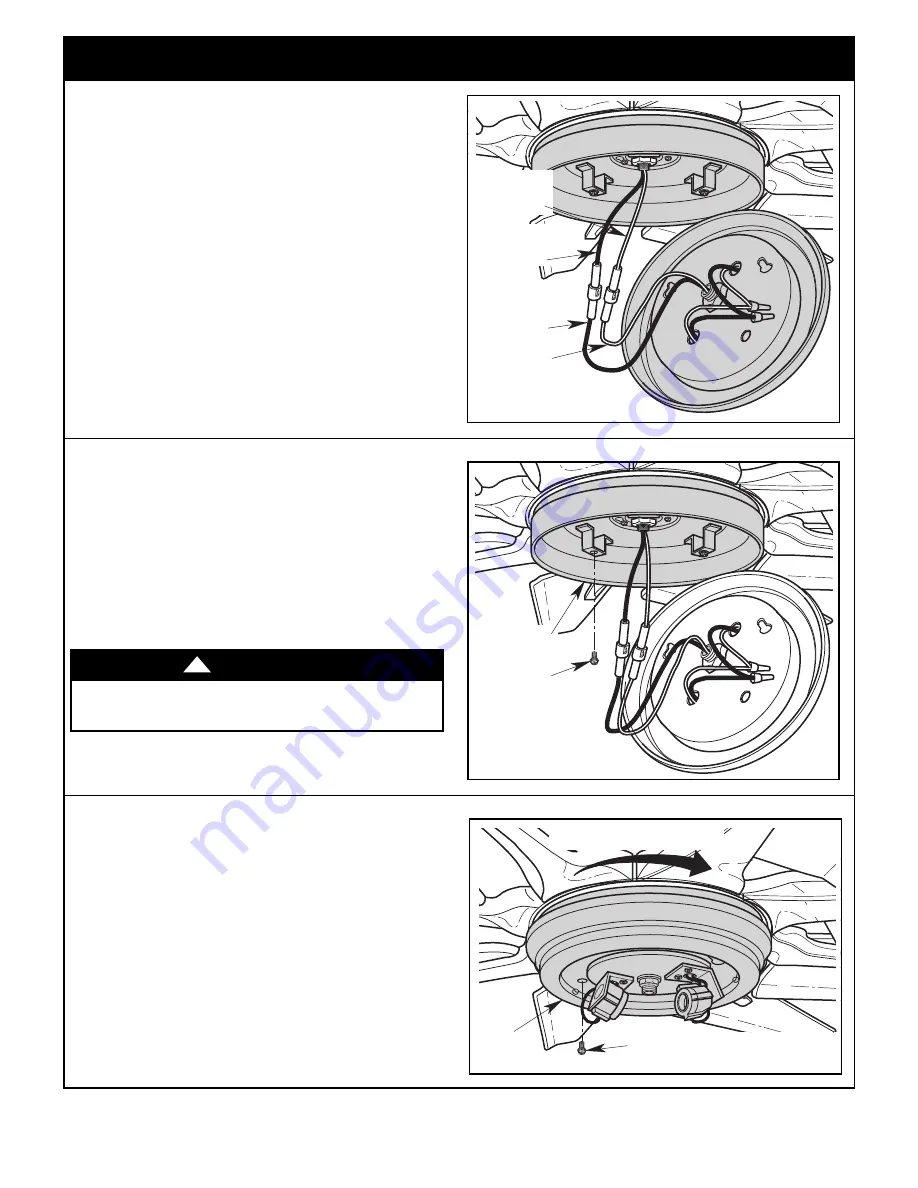
8. Installation of Downlight Assembly
(Continued)
8.5
Install the light fitter onto the light fitter housing by aligning
and engaging the keyhole slots of the light fitter with the
loosened screw heads on the light fitter housing
(Figure 27).
Rotate the light fitter clockwise to engage the two loosened
screws.
With the light fitter locked into position, tighten the two
previously loosened screws.
Reinstall the #6-32 x 3/8” truss head screw with
lockwasher (previously removed) into the light fitter
(Figure 27).
LIGHT
FITTER
ROTATE LIGHT FITTER CLOCKWISE TO
ENGAGE THE TWO LOOSENED SCREWS
REINSTALL ONE #6-32 x 3/8” TRUSS
HEAD SCREW WITH LOCKWASHER
Figure 27
8.3
Connect the white wire from the fan motor assembly to the
white wire of the light fitter (Figure 25).
Connect the black wire from the fan motor assembly to the
black wire of the light fitter (Figure 25).
LIGHT FITTER
HOUSING
WHITE WIRE
LIGHT FITTER
HOUSING
BLACK WIRE
FAN MOTOR
ASSEMBLY
BLACK WIRE
FAN MOTOR
ASSEMBLY
WHITE WIRE
Figure 25
To avoid possible fire or shock, do not pinch wires
between the light fitter housing and the light fitter.
WARNING
!
8.4
Remove one of the three #6-32 x 3/8” truss head screw
with lockwasher from the light fitter housing (Figure 26).
Retain the screw for future installation.
Loosen the other two screws several turns.
Carefully tuck all the wires and connectors under the light
fitter and place the light fitter onto the light fitter housing.
REMOVE ONE
#6-32 x 3/8"
TRUSS HEAD
SCREW WITH
LOCKWASHER
LIGHT FITTER
HOUSING
Figure 26
Spare #6-32 x 3/8” truss head screw with lockwasher is
provided in parts bag if needed.


