11
emersonfans.com
Please contact 1-800-654-3545 for further assistance
ETL Model No.: CF880
Using Your Ceiling Fan
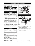
THREADED
STUDS (2)
CEILING COVER
KNURLED KNOBS (2)
LOCKWASHERS (2)
Figure 16
1.
Push the wires and connectors up into the outlet box
while inserting the receiver fully into the hanger
bracket.
2
Position the antenna wire on top of the receiver.
3.
Screw the two threaded studs (supplied) into the
tapped holes in the hanger bracket.
4.
Lift the ceiling canopy up to the threaded studs and
turn until studs protrude through the holes in the
ceiling canopy (Figure 16).
5.
Secure the ceiling canopy in place by sliding
lockwashers over the threaded studs and installing
the two knurled knobs (supplied). (Figure 16).
Tighten the knurled knobs securely until the ceiling
canopy fits snugly against the ceiling and the hole in
the ceiling canopy is clear of the downrod.
General
This control is designed to operate only one ceiling fan
6.
Before disconnecting power, ensure that the fan is
set at the highest speed.
NOTE: Electric connections should be in
accordance with the National Electrical Codes and
all Local Codes. Before starting, disconnect power
to the circuit at the fuse box or circuit breaker
panel.
7.
Remove the faceplate and screws from the existing
wall switch. Pull switch out from wall outlet box
(Figure 17).
8.
Disconnect wire from existing fan wall switch.
Setting Operating Frequency of
Wall Control
Your wall control has code switches which must be set
in one of 32 possible code combinations. The five levers
(numbered 1, 2, 3, 4, and 5) on the switches are factory-
set in the ON (up) position (Figure 18). Change the
switch settings as follows:
9.
Slide the five switch levers in the wall control to your
choice of ON (up) or down positions. Use a ball-
point pen or small screwdriver and slide the levers
firmly up or down.
10.
When the power is restored after installation, push
and hold the fan off button ( ) for 3 to 5 seconds
to set the code in the receiver.
To avoid possible fire or shock, make sure that the
electrical wires are completely inside the outlet box and
not pinched between the ceiling cover and the ceiling.
WARNING
!
FACEPLATE
SWITCH
WALL
OUTLET
BOX
Figure 17
CODE
SWITCHES
WALL
CONTROL
WALL CONTROL
CODE SWITCHES
ON
1
2
3
4 5
I
Figure 18
11.
The sixth switch marked ON and I is for dimming
control of lights: Set switch to ON to allow for
dimming of the lights.
NOTE: Use wire connectors (supplied) to secure
electrical connections.
Summary of Contents for AMHURST CF880BS00
Page 18: ...18 ETL Model No CF880 Notes ...


