4
1
6
9
8
27
21
19 20
18
7
2
5
4
11
14
13
17
12
16
10
23
24
16
25 26
ANDERSON GREENWOOD
SERIES 96A VACUUM BREAKER
INSTALLATION AND MAINTENANCE INSTRUCTIONS
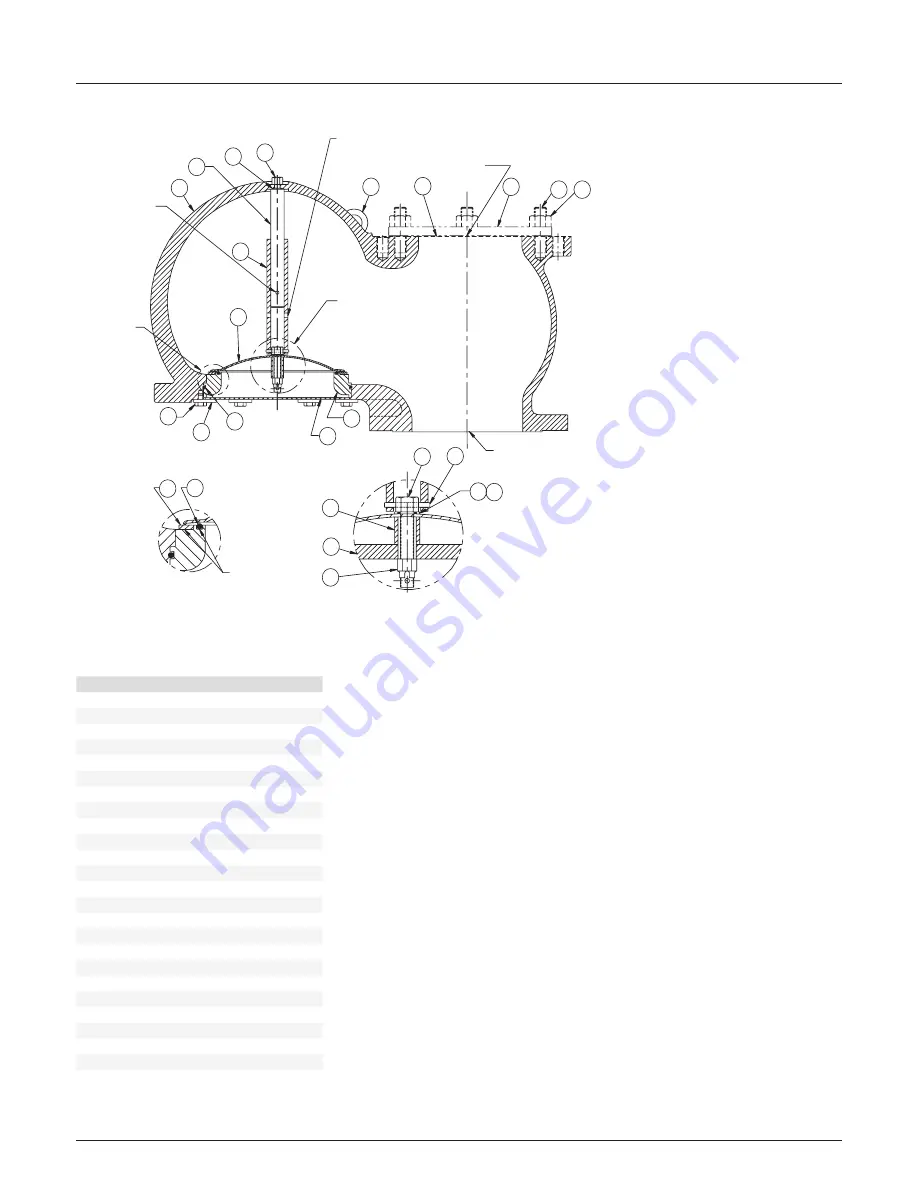
PARTSLIST
Item
Description
1
Body
2
Nut-lock
4
Pin-spring
5
Bolt-seat bolt
6
Rod-guide
7
Tube-guide
8
Bolt-guide rod
9
O-ring
10
Seat-sponge
11
Plate-seat
12
Screen-inlet
13
Retainer-seat ring
14
Bolt-retainer
15
Ring-seat
16
O-ring, Seat plate
17
O-ring, Seat ring
18
Cap-outlet
19
Stud
20
Nut
21
Gasket
23
Weight-ring
24
Spacer
25
Retainer-O-ring
26
O-ring
27
Eyebolt
ø.249 - .269 (ø6.32 - 6.83 mm)
Cross drill hole
ø.280 - .288
(ø7.11 - 7.32 mm)
Cross drill hole
See detail B
See detail A
Relief valve connection, 150 # FFSF
Tank connection
½ oz set
(0.22 kpag)
Apply adhesive
to this surface
Detail A
1½ oz set (0.65 kpag)
Detail B
FIGURE 1


