background image

Appleton • 1.800.621.1506 • www.appletonelec.com

650525-001 Rev. B 10/16 • Page 1 of 1

650525-001 INSTRUCTION SHEET

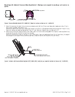
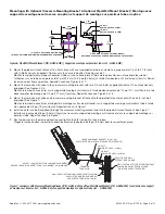
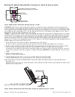
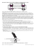
Installation Instructions for Appleton™ Areamaster™ GEN 2 LED Luminaire -  
Yoke Mount

FOR PROPER AND SAFE INSTALLATION OF THIS PRODUCT, PLEASE READ THE FOLLOWING INSTRUCTIONS.

Product Safety

Signal Words Defined

DANGER

 indicates a hazardous situation which, if not avoided, will result in death or serious injury. 

WARNING

 indicates a hazardous 

situation which, if not avoided, could result in death or serious injury. 

CAUTION

 indicates a hazardous situation which, if not avoided, 

could result in minor or moderate injury. 

NOTICE

 is used to address practices not related to physical injury.

Safety Instructions

 WARNING: 

•  Do not open or remove luminaire with the circuit energized.

•  Do not remove or replace fuse when luminaire is energized.

•  Do not use this luminaire on ungrounded systems. Failure to ground this luminaire can result in an electric shock, which may be fatal.

•  Do not use on ungrounded 480 Volt circuits.

 CAUTION:

•  Do not look directly at the LEDs when energized.

 NOTICE:

•  Do not touch the LEDs; touching could leave oily deposits, causing hot spots and potential premature failure.

•  This product must be installed in accordance with the applicable installation code by a person familiar with the construction and 

operation of the product and the hazards involved.

•  This luminaire is designed for and should be installed in accordance with the National Electrical Code

®

/Canadian Electrical Code 

and all applicable local codes.

Marine & Hazardous Locations

 CAUTION/ATTENTION: 

•  To reduce the risk of ignition of hazardous atmospheres, disconnect the luminaire from the supply circuit before opening. Keep 

tightly closed when in operation. 

  Pour réduire le risque d’inflammation/explosion en atmosphères explosibles, isoler le luminaire du circuit d’alimentation avant 

ouverture. Veillez à ce que le luminaire soit correctement fermé avant la mise sous tension.

•  Make sure to tighten unused close-up plug to 400 in.-lb. after applying TLNC4 grease. TLNC4 grease shall be applied in 3 lines, 

spaced approximately 120 degrees apart, perpendicular to the threads.

•  Where flexible cord is used, it should be approved for extra hard, wet location usage and shall have a separate ground conductor.

Agency Ratings: (NEC/CEC)

•  Class 

I

, Division 2, Groups A, B, C, & D

•  Class 

II

, Division 1, Groups E, F, & G

•  Class 

II

, Division 2, Groups F & G

•  Class 

III

•  Simultaneous Exposure
•  Class 

I

, Zone 2, Group 

II

C

•  Zone 20, Group 

III

C

•  Zone 21, Group 

III

C

•  Zone 22, Group 

III

B

•  Wet Locations
•  Marine Outside Type (Salt Water) (For installation in USA only)
•  Type 3R, 4, & 4X
•  IP66 & IP67

Summary of Contents for Appleton Areamaster GEN 2 LED Series

Page 1: ...be installed in accordance with the applicable installation code by a person familiar with the construction and operation of the product and the hazards involved This luminaire is designed for and should be installed in accordance with the National Electrical Code Canadian Electrical Code and all applicable local codes Marine Hazardous Locations CAUTION ATTENTION To reduce the risk of ignition of ...

Page 2: ...hez pas les LED au risque de laisser des dépôts huileux qui causent des points chauds et d éventuelles défaillances prématurées Ce produit doit être installé conformément au code d installation applicable par une personne connaissant la construction et le fonctionnement du produit et les risques encourus Ce luminaire est conçu pour être installé conformément au National Electrical Code Code canadi...

Page 3: ... 2B 1 4 20 2 HUBS FOR 3 4 NPT CONDUIT 2 ORIFICES POUR CONDUIT NPT 3 4 PO 3 MOUNTING HOLES 0 56 DIA 3 TROUS DE MONTAGE DE 14 2 MM DE DIAMÈTRE 6 0 TURNING RADIUS 180 ROTATION RAYON DE GIRATION DE 152 MM ROTATION DE 180 6 00 13 84 5 05 12 94 16 28 2 25 1 75 3 50 4 YOKE BOLTS 4 BOULONS D ÉTRIER 6 16 SQUARE CARRÉ DE 156 5 mm Figure 1 Areamaster GEN 2 LED Luminaire Luminaire Areamaster à LED de 2e GÉNÉR...

Page 4: ...3 MOUNTING HOLES 0 56 DIA 3 TROUS DE MONTAGE DE 14 2 MM DE DIAMÈTRE Figure 2 Luminaire with Yoke Luminaire avec étrier Mounting with Yoke Montage avec étrier 1 Mount the luminaire with yoke to a flat surface using user supplied hardware See Figure 2 for mounting hole locations Montez le luminaire avec étrier sur une surface plate à l aide de quincaillerie fournie par l utilisateur Reportez vous à ...

Page 5: ...à l aide de deux boulons de montage de 1 2 po 12 7 mm fournis et de deux rondelles de blocage de 1 2 po 12 7 mm fournies Reportez vous aux Figures 4 et 5 2 Mount the crossarm mounting bracket to a flat surface with one 3 4 inch bolt not supplied The crossarm mounting bracket may be locked into position with a 3 8 inch bolt not supplied Montez le support de montage sur traverse sur une surface plat...

Page 6: ...lons de 1 2 po 12 7 mm fournis et de deux rondelles de blocage de 1 2 po 12 7 mm fournies Reportez vous aux Figures 4 et 5 5 Mount the luminaire with yoke and crossarm mounting bracket attached to the pipe wall mount bracket with one 3 4 inch bolt supplied See Figure 7 Montez le luminaire avec étrier et support de montage sur traverse attaché sur le support de montage sur paroi sur tube à l aide d...

Page 7: ...ple de 45 2 N m après y avoir appliqué de la graisse TLNC4 La graisse TLNC4 doit être appliquée en 3 lignes perpendiculaires au filetage espacées les unes des autres d environ 120 1 Loosen the two screws on the pressure plate for cord cable entrance See Figure 8 Desserrez les deux vis de la plaque de pression pour permettre l entrée du cordon câble Reportez vous à la Figure 8 2 Feed the supply cor...

Page 8: ... perpendiculaires au filetage espacées les unes des autres d environ 120 1 Loosen the two screws on the pressure plate for cord cable entrance See Figure 10 Desserrez les deux vis de la plaque de pression pour permettre l entrée du cordon câble Reportez vous à la Figure 10 2 Feed the supply cord cable up through the poletop slip fitter and out through the cord grip assembly Leave at least 10 inche...

Page 9: ... through the conduit entry with appropriate fitting attached to the luminaire wiring compartment Insérez le câble par l entrée de câble avec le raccord approprié attaché jusqu au compartiment de câblage du luminaire B Wiring with Individual Conductor Wire Raccordement à l aide d un fil à conducteur individuel 1 Run conductors down through the conduit to the luminaire wiring compartment Acheminez l...

Page 10: ...être appliquée en 3 lignes perpendiculaires au filetage espacées les unes des autres d environ 120 7 Power can now be applied to the luminaire Le luminaire peut maintenant être mis sous tension WIRING COMPARTMENT WITH OPEN LID COMPARTIMENT DE CÂBLAGE AVEC COUVERCLE OUVERT 4 CAPTIVE SCREWS 4 VIS IMPERDABLES FUSE AND FUSE HOLDER FUSIBLE ET PORTE FUSIBLES LED ARRAY WITH OPTICS RÉSEAU DE LED AVEC OPTI...

Page 11: ...ienced in the use and maintenance of this equipment and not for consumers or consumer use Appleton warranties DO NOT extend to and no reseller is authorized to extend Appleton s warranties to any consumer While every precaution has been taken to ensure accuracy and completeness in this manual Appleton Grp LLC assumes no responsibility and disclaims all liability for damages resulting from use of t...

Page 12: ...E CÔTÉ ENTRÉE PRINCIPAL NOIR PHASE BLANC NEUTRE VERT TERRE CIRCUIT DE LED AVEC FUSIBLE ET DISPOSITIF DE PROTECTION CONTRE LES SURTENSIONS Figure 15 Schémas de câblage Remplacement du fusible Ne remplacez que par un fusible de calibre intensité et tension spécifié sur l étiquette de fusible située à l intérieur du boîtier du luminaire Le fusible de remplacement ne doit pas produire d arc électrique...

Reviews: