INSTALLATION
Series 185
1
381333–319 D
Installation of the ASCO Series 185 automatic transfer
switch (ATS) must be performed by a licensed electrician.
It must be installed according to the National Electrical
Code (NEC) and all local electrical code requirements.
Remove the enclosure cover and inspect the ATS for
shipping damage. If damage is evident do not install the
ATS.
1 --- Mounting
Refer to the enclosure outline drawing. Mount the ATS
according to details and instructions shown on this
diagram. Mount the ATS vertically to a rigid supporting
structure. Level all mounting points by using flat washers
behind the holes to avoid distortion of the enclosure.
MALFUNCTION or SHORTENED LIFE
Protect the ATS from construction grit and metal
chips to prevent malfunction or shortened life.
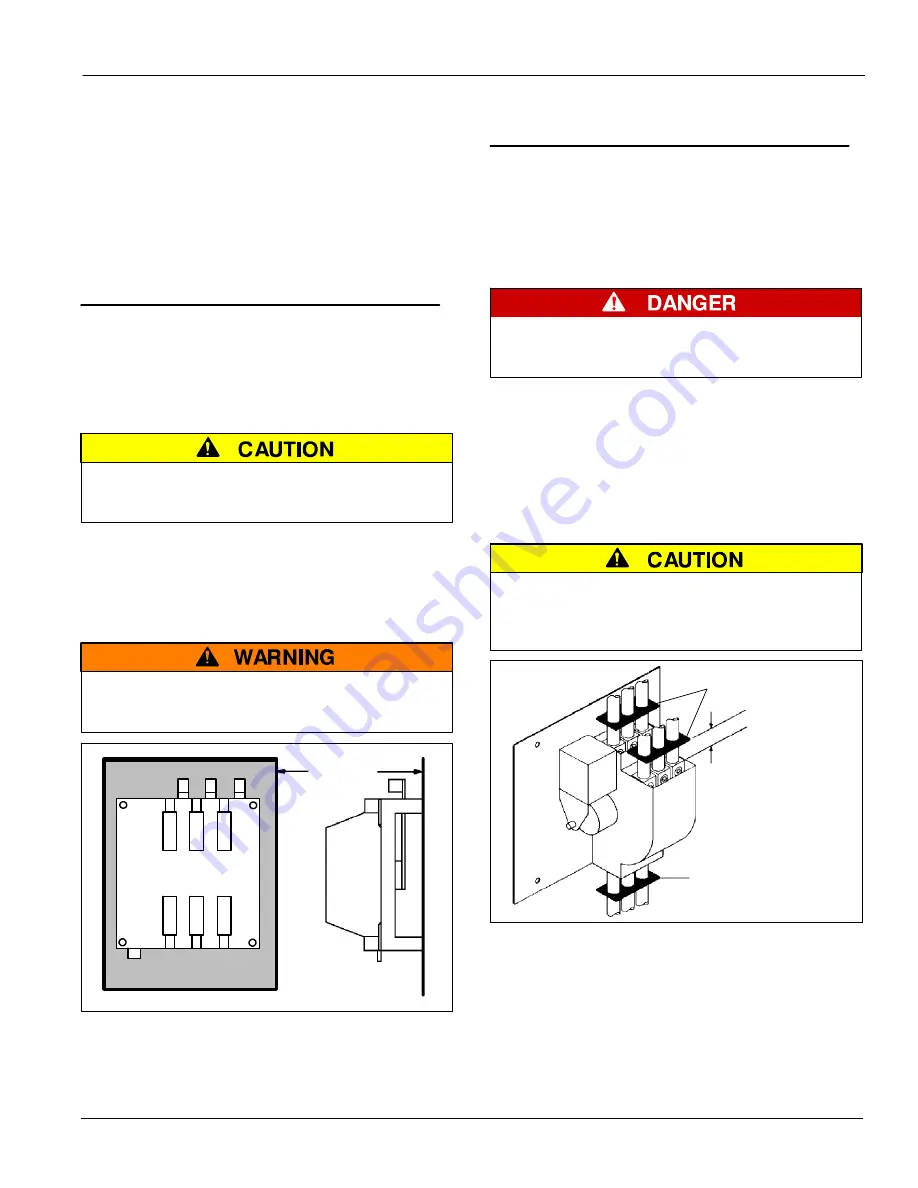
Transfer switches rated 260 and 400 amperes are
mounted on an insulator backing piece (installed behind
the transfer switch). If the transfer switch is removed
from the enclosure and then reinstalled, this insulator
must be placed behind the transfer switch. See Figure 1.
FLASH HAZARD – DAMAGE
Be sure that the insulator piece is installed behind
the 260 and 400 ampere transfer switches.
insulator
backing
piece
Figure 1. Insulator for 260 and 400 A.
2 --- Electrical Power Connections
Refer to the wiring diagram. The ATS must be protected
by suitably sized circuit breakers feeding the utility and
generator source terminals. The rating of the circuit
breakers must be based on the requirements of the
National Electrical Code for its nameplate ampere and
short circuit withstand ratings.
ELECTROCUTION HAZARD Turn off utility
power and turn off the generator to prevent
electrocution when wiring the transfer switch.
Cable Spacers for 200 and 230 A
Three cable spacers are included with 200 and 230
ampere transfer switches. Run the copper power cables
through the cable spacers as shown in Figure 2. Position
the cable spacers approximately 1½ inches from the
terminal lugs.
CABLE LOOSENING DUE TO SHORT CIRCUIT
Install three cable spacers 1 1/2 inches from
the power terminals to prevent the cables from
loosening during a short–short condition.
cable spacer
cable spacers
1 ½ inch approximate
use copper power
cables only for
200 and 230 A
Figure 2. Cable spacers for 200 and 230 A.


