Fig. 9:
Microprocessor Controller
Retransfer to
Normal Adjustable
Time Delay
Transfer to
Emergency Adjustable
Time Delay
Performance Features
n
600 volt spacing per UL and CSA standards.
n
Interfacing relays are industrial grade, plug-in type with dust covers.
n
Meets or exceeds the requirements for Electromagnetic Compatibility (EMC).
Simple and Accurate
Adjustment of
Voltage, Frequency
and Time-Delay
Settings Without
Need for Meters
and Variable
Power Supplies
Battery to
Maintain Engine
Exerciser Clock
Settings
Serial
Communication Port
Dip Switches for Enabling
Built-In Control Functions
Customer Control
Interfaces
l
ANSI C37.90A/IEEE472 Voltage
Surge Test
l
NEMA ICS-109.21 Impulse
Withstand Test
l
Digital circuitry isolated from
line voltages
l
IEC 801-2 Electrostatic
discharge (ESD) immunity
l
ENV50140 and IEC 803-1: Radiated
electromagnetic field immunity
l
IEC 801-4 Electrical fast transient (EFT)
immunity
l
ENV50142 Surge transient immunity
l
ENV50141: Conducted
radio-frequency field immunity
l
EN55011: Group 1, Class A conducted and
radiated emissions
l
Optically isolated RS-485 Serial Port
l
EN61000- 4-11 voltage dips and interruptions
immunity
7
Electrical Features:
l
Listed under UL 1008, CSA certified:
- UL listed through 480 VAC.
- CSA certified through 600 VAC.
l
Door-mounted selector switch for local, manually initiated
electrical control.
l
Sizes from 30 through 3000 amps.
l
Available to 600 VAC, 50 or 60 Hz.
l
Rated for all classes of load transfer.
l
100% tungsten load ratings through 400 amps.
l
Designed for emergency and standby applications.
l
Same withstand and close-on rating as Series 300.
Standard Selectable Control Features:
l
Inphase monitor to transfer motor loads between live
sources, without any intentional off time, to prevent
inrush currents from exceeding normal starting levels.
l
Selective load disconnect, double-throw contact to
operate at an adjustable 0 to 20 second time delay prior
to transfer and reset 0 to 20 seconds after transfer.
l
High/Low nominal voltage setting. Allows user to adjust
for source low reduced voltage conditions in remote areas.
l
60 Hz or 50 Hz selectable switch.
l
Single/Three-phase selectable switch.
Control Features:
l
Switch position indicating signal lights.
l
One auxiliary contact closed when transfer switch is
connected to normal and one closed on emergency,
standard feature 14A/14B.
Optional Accessories:
l
6Q Key-operated, momentary source selector switch
furnished instead of the standard selector switch.
l
9C, 9D Source availability lights to provide operator with
a local indication of power source availability.
l
Accessory 14AA/14BA auxiliary contacts to indicate
position of main contacts. Two (2) for normal position and
two (2) for emergency position (one set is standard).
l
72A Communications interface module (RS-485) to allow
local or remote communications with ASCO
Power
Quest
®
VP
i
or
Site
Web™ communication products.
l
Special Enclosures
(Specify by appropriate code in catalog number):
Type 3R: Raintight
Type 4: Weatherproof
Type 12: Oil Tight
User-Initiated Control
ASCO 386 non-automatic transfer switches are generally used in applications where operating personnel are
available and the load is not an emergency type requiring automatic transfer of power. The power-switching
mechanism and controller is the same hardware used on the highly reliable ASCO Series 300 transfer switches.
ASCO 386s are furnished as standard with a momentary-type selector switch to initiate transfer and retransfer.
They can also be arranged for remote control via ASCO s communication products.
The ASCO Service Entrance
Power Transfer Switch
combines automatic
power switching with a utility circuit breaker as a disconnect
device. The power transfer switch meets all National
Electrical Code requirements for installation as service
entrance equipment.
Service entrance rated transfer switches generally are
installed at facilities that have a single utility feed and
a single emergency power source. A circuit breaker serves
as the utility disconnect
and links are provided to
connect both neutral and
ground conductors.
The ASCO 300SE Service
Entrance Automatic Transfer
Switch uses the same
reliable transfer switching
mechanism and controller
as the series 300 product
platform, and also includes
a utility circuit breaker as
a disconnect device.
Product Features:
l
Suitable for use as service entrance equipment.
l
The ASCO Series 300SE is listed to UL 891 standard
for Dead-Front Switchboards, and meets all NEC
requirements for service entrance equipment.
l
Automatic Transfer Switch is listed to UL 1008 for total
system loads.
l
Sizes available from 70 through 3000 amps.
l
Available to 600 VAC, 50 or 60Hz, single or three phase.
l
Circuit Breaker disconnect on the normal for isolation of
transfer switch and other electrical equipment.
l
Disconnect link on Neutral and Ground.
l
Silver plated copper ground and neutral bus.
l
Solderless screw type terminals for External Power
Connections.
l
Ground fault trip protection provided on sizes of 1000
amperes and above.
l
UL approved Type 1 enclosure.
l
Available with solid or switched neutral.
l
Optional TVSS Available on Normal, Emergency and/or Load.
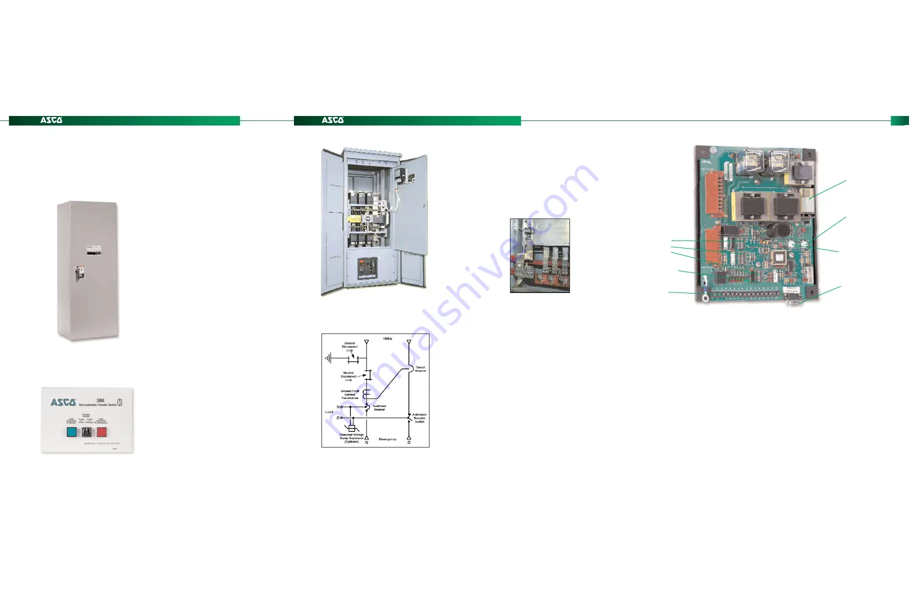
Fig. 14:
Control and Display Panel
Series 386
Non-Automatic Power Transfer Switches
Series 300SE
Power Transfer Switch
Fig. 13:
ASCO 386 400 Amp
Type 1 Enclosure w/Optional
Accessories 9C, 9D Source
Availability Lights
11
12
Fig. 15:
ASCO Service Entrance Power
Transfer Switch rated 3 Pole 2000
amperes shown in Type 3R secured
double door enclosure with solid neutral
One line diagram of a typical service entrance rated
transfer switch available in Solid or Switched Neutral
Fig. 16:
Rear views showing
ground fault protection
with ground and neutral
disconnect links


