Chapter 3
ATCA-7368 Installation and Use (6806800M12C)
51
Controls, Indicators, and Connectors
3.1
Overview
This chapter describes the LEDs, connectors, and external interfaces of the board.
3.2
Faceplate
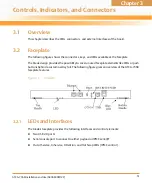
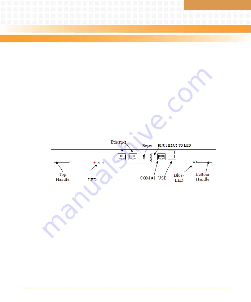
The following figure shows the connectors, keys, and LEDs available at the Faceplate.
The blade design provides the possibility to cover unused Faceplate elements like LEDs or push
buttons behind a custom overlay foil. The following figure gives an overview of the ATCA-7368
faceplate features.
3.2.1
LEDs and Interfaces
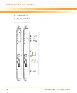
The blade's faceplate provides the following interfaces and control elements:
Two USB 2.0 ports
Serial console port to connect to either payload or IPMC serial I/F
Out of Service, In Service, Attention, and Hot Swap LEDs (IPMC control)
Figure 3-1
Faceplate
Summary of Contents for ATCA-7368
Page 8: ...ATCA 7368 Installation and Use 6806800M12C Contents 8 Contents Contents ...
Page 14: ...ATCA 7368 Installation and Use 6806800M12C 14 List of Figures ...
Page 50: ...Hardware Preparation and Installation ATCA 7368 Installation and Use 6806800M12C 50 ...
Page 88: ...Functional Description ATCA 7368 Installation and Use 6806800M12C 88 ...
Page 210: ...Replacing the Battery ATCA 7368 Installation and Use 6806800M12C 210 ...
Page 221: ......

