Hardware Preparation and Installation
ATCA-7368 Installation and Use (6806800M12C)
41
Removal Procedure
To remove a DIMM module, proceed as follows:
1. Remove blade from system as described in
Installing and Removing the Blade
2. Open locks of socket at both sides.
The memory module is automatically lifted up.
3. Remove module from socket.
4. Repeat steps 2 to 3 in order to remove further memory modules.
2.5.2
PMEM and SATA Module
The PMEM/SATA extension slot allows assembly of either a PMEM or SATA module which are
available as upgrade kits for ATCA-7368. The PMEM module consists of an SRAM and a flash
memory. The SRAM has a capacity of up to 16 MB and can be used as persistent memory, i.e. a
memory that holds up the contents during reset. The flash memory has a capacity of up to 64
MB organized as two memory banks. The S/F memory module connects to the blade's PCI
subsystem. It can be configured via an FPGA register.
The SATA module consists of a Solid State Disc of up to 128 GB and a SATA controller and
connects physically to ICH10 SATA Port #5.
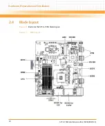
The extension module is mechanically fastened to the blade with two screws. The location of
the two corresponding mounting holes as well as the S/F memory module connector is shown
in
Figure "Blade Layout" on page 38
The PMEM and SATA module are accessory kits and are not part of the default ATCA-7368. The
following procedure describes the steps to install/remove the PMEM/SATA module.
Summary of Contents for ATCA-7368
Page 8: ...ATCA 7368 Installation and Use 6806800M12C Contents 8 Contents Contents ...
Page 14: ...ATCA 7368 Installation and Use 6806800M12C 14 List of Figures ...
Page 50: ...Hardware Preparation and Installation ATCA 7368 Installation and Use 6806800M12C 50 ...
Page 88: ...Functional Description ATCA 7368 Installation and Use 6806800M12C 88 ...
Page 210: ...Replacing the Battery ATCA 7368 Installation and Use 6806800M12C 210 ...
Page 221: ......


