Intelligent Peripheral Management Controller
ATCA-8310 Installation and Use (6806800M72D)
207
7.5.3
POST Results Sensor
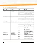
The POST results sensor is of type 0x28 (Management subsystem health) returning information
about whether the power-on self-test (POST) of the IPMI firmware passes or not. For more
details about the POST, refer to
.
7.5.4
Power Good Sensor
The Payload Power sensor is of type 0x08 (Power Supply) which reports the state of the payload
power. Since the Digital Power Monitor can disable payload power on its own due to a faulty
DC-DC converter, the IPMC monitors the health and will report an event in the case where the
Digital Power Monitor disables power on its own. As a result of this, the IPMC will proactively
transition the IPMC from M4 to M6 (to M1) with a cause code of 0x09 (Unexpected
Deactivation). This automatic shutdown is meant to keep the IPMC's state in-line with the
payload state.
7.5.5
SW Progress Sensors
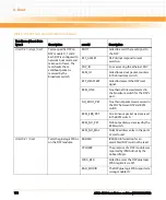
The SW progress sensors are implemented to enable the customer to report software specific
states for initialization and high availability purpose. The ATCA-8310 provides 3 universal
sensors ready to be used by the customer. The sensor state definition is customer specific.
The sensors can be feeded by executing the OEM specific IPMI command "Send SW Progress
Data".
7.5.6
Power Interface Sensors
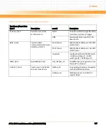
Depending on the board revision, either an Emerson (IPM300) or a PowerOne (Synqor) power
entry module is used for the 48v to 12v conversion. These include sensors which monitor the
shelf's 48v input feeds current, hold-up capacitor voltage, on-board temperature, and internal
status. Its status sensor reading can be decoded as provided in
.
The IPMC is dynamically deciding at run-time which power entry module is used.
Summary of Contents for ATCA-8310
Page 12: ...ATCA 8310 Installation and Use 6806800M72D Contents 12 Contents Contents ...
Page 26: ...ATCA 8310 Installation and Use 6806800M72D 26 List of Figures ...
Page 34: ...ATCA 8310 Installation and Use 6806800M72D About this Manual 34 About this Manual ...
Page 54: ...Hardware Preparation and Installation ATCA 8310 Installation and Use 6806800M72D 54 ...
Page 70: ...Controls Indicators and Connectors ATCA 8310 Installation and Use 6806800M72D 70 ...
Page 162: ...BIOS ATCA 8310 Installation and Use 6806800M72D 162 ...
Page 200: ...U Boot ATCA 8310 Installation and Use 6806800M72D 200 ...
Page 244: ...Intelligent Peripheral Management Controller ATCA 8310 Installation and Use 6806800M72D 244 ...
Page 438: ...CPLD and FPGA ATCA 8310 Installation and Use 6806800M72D 438 ...
Page 442: ...Replacing the Battery ATCA 8310 Installation and Use 6806800M72D 442 ...
Page 444: ...Related Documentation ATCA 8310 Installation and Use 6806800M72D 444 ...
Page 454: ...ATCA 8310 Installation and Use 6806800M72D Sicherheitshinweise 454 ...
Page 456: ...Index ATCA 8310 Installation and Use 6806800M72D 456 ...
Page 457: ...Index ATCA 8310 Installation and Use 6806800M72D 457 ...
Page 458: ...Index ATCA 8310 Installation and Use 6806800M72D 458 ...
Page 459: ......

