Controls, Indicators, and Connectors
ATCA-8310 Installation and Use (6806800M72D)
67
3.4.4
VGA Connector
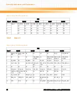
TSIP1_RX-
143
144
TSIP1_TX-
V1P2
145
146
V1P2
T
147
148
T
TSIP0_RX-
149
150
TSIP0_TX-
V1P2
151
152
V1P2
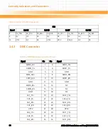
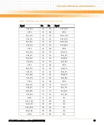
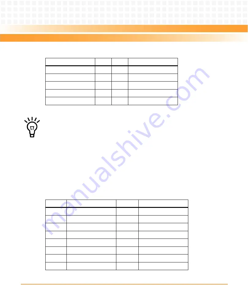
Table 3-7 DMC Mezzanine Connector Pinout (continued)
Signal
Pin
Pin
Signal
The pinouts on
applies to both mezzanine connectors. The signal names
are then named DMC1… DMC2…
Table 3-8 VGA Connector Pinout
Pin
Signal
Pin
Signal
1
CRT-RED
9
VP5
2
CRT-GREEN
10
GND
3
CRT-BLUE
11
NC
4
NC
12
DDC-DATA
5
GND
13
CRT-HSYNC
6
GND
14
CRT-VSYNC
7
GND
15
DDC-CLK
8
GND
Summary of Contents for ATCA-8310
Page 12: ...ATCA 8310 Installation and Use 6806800M72D Contents 12 Contents Contents ...
Page 26: ...ATCA 8310 Installation and Use 6806800M72D 26 List of Figures ...
Page 34: ...ATCA 8310 Installation and Use 6806800M72D About this Manual 34 About this Manual ...
Page 54: ...Hardware Preparation and Installation ATCA 8310 Installation and Use 6806800M72D 54 ...
Page 70: ...Controls Indicators and Connectors ATCA 8310 Installation and Use 6806800M72D 70 ...
Page 162: ...BIOS ATCA 8310 Installation and Use 6806800M72D 162 ...
Page 200: ...U Boot ATCA 8310 Installation and Use 6806800M72D 200 ...
Page 244: ...Intelligent Peripheral Management Controller ATCA 8310 Installation and Use 6806800M72D 244 ...
Page 438: ...CPLD and FPGA ATCA 8310 Installation and Use 6806800M72D 438 ...
Page 442: ...Replacing the Battery ATCA 8310 Installation and Use 6806800M72D 442 ...
Page 444: ...Related Documentation ATCA 8310 Installation and Use 6806800M72D 444 ...
Page 454: ...ATCA 8310 Installation and Use 6806800M72D Sicherheitshinweise 454 ...
Page 456: ...Index ATCA 8310 Installation and Use 6806800M72D 456 ...
Page 457: ...Index ATCA 8310 Installation and Use 6806800M72D 457 ...
Page 458: ...Index ATCA 8310 Installation and Use 6806800M72D 458 ...
Page 459: ......


