background image

ATCA-F120 Installation and Use (6806800D06F)

About this Manual

16


About this Manual


Summary of Changes

This manual has been revised and replaces all prior editions.

Part Number

Publication Date

Description

6806800D06A

April 2007

First draft (DA release version)

6806800D06B

September 2007

EA version
Changes made compared to previous version 
include: updated standard requirements, 
updated power requirements, updated 
environmental requirements, enhanced 
block diagram figures (fabric and base 
interface connections as well as shelf 
manager cross-connection figures), updated 
IPMI sensor list, added blackplane connector 
pinouts, added section: "Boot and User 
Flashes", added figure which shows the 
location of on-board switches.

Summary of Contents for ATCA-F120

Page 1: ...Embedded Computing for Business Critical ContinuityTM ATCA F120 Installation and Use P N 6806800D06F February 2009 ...

Page 2: ...s document and to make changes from time to time in the content hereof without obligation of Emerson to notify any person of such revision or changes Electronic versions of this material may be read online downloaded for personal use or referenced in another document as a URL to a Emerson website The text itself may not be published commercially in print or electronic form edited translated or oth...

Page 3: ...7 2 1 Overview 37 2 2 Unpacking and Inspecting the Blade 37 2 3 Environmental and Power Requirements 38 2 3 1 Environmental Requirements 38 2 3 2 Power Requirements 41 2 4 Installing Rear Transition Modules 42 2 5 Configuring the Blade 42 2 6 Blade Installation and Removal 45 2 6 1 Installing the Blade 46 2 6 2 Removing the Blade 49 2 7 AMC Modules 50 2 7 1 Supported AMC Modules 52 2 7 1 1 AMC Bay...

Page 4: ...2 LEDs 72 3 4 Rear Panel 74 4 Functional Description 79 4 1 Overview 79 4 2 Block Diagram 80 4 3 Central Processing Unit 80 4 4 Main Memory 81 4 5 Glue Logic FPGA 81 4 5 1 General Features 82 4 5 2 Watchdog 82 4 6 Boot and User Flashes 83 4 6 1 Boot Flashes 83 4 6 2 User Flashes 83 4 7 Fabric Channel Interfaces 84 4 8 Base Channel Interfaces 89 4 9 Base Interface Extension 92 4 9 1 Port Assignment...

Page 5: ...from Flash 105 5 4 Selecting the Boot Flashes 106 5 5 Using the Persistent Memory Feature 107 5 6 Memory Map 109 5 7 Linux Devices 110 5 8 Power On Self Test 111 5 8 1 POST Routines 113 5 8 2 Controlling the Execution of the POST 114 5 9 Product Name Short Specific U Boot Commands 114 5 10 Product Name Short Specific U Boot Environment Variables 115 5 11 Updating U Boot 117 A Related Documentation...

Page 6: ...ATCA F120 Installation and Use 6806800D06F Contents 6 Contents Contents ...

Page 7: ...late LEDs 74 Table 4 1 Main Features of Fabric Channel Interface Switches 84 Table 4 2 FIX 1 Ethernet Port Assignment 87 Table 4 3 FIX 2 Ethernet Port Assignment 88 Table 4 4 Base Channel Switch Port Assignment 91 Table 4 5 Base Interface Extension Port Assignment 92 Table 4 6 On Board Memory of IMC ISC0 1 and MMC 96 Table 4 7 IPMI Sensors Overview 98 Table 5 1 Physical Address Map 109 Table 5 2 L...

Page 8: ...ATCA F120 Installation and Use 6806800D06F 8 List of Tables ...

Page 9: ...annel Extension Connector 72 Figure 3 7 Face Plate LEDs 73 Figure 3 8 Location of AdvancedTCA Connectors 75 Figure 3 9 P30 Connector Pinout Columns A to D 76 Figure 3 10 P30 Connector Pinout Columns E to H 76 Figure 3 11 P31 Connector Pinout Columns A to D 77 Figure 3 12 P31 Connector Pinout Columns E to H 77 Figure 3 13 P32 Connector Pinout Columns A to D 78 Figure 3 14 P32 Connector Pinout Colum...

Page 10: ...ATCA F120 Installation and Use 6806800D06F 10 List of Figures ...

Page 11: ... z Chapter 3 Controls LEDs and Connectors on page 61 describes external interfaces of the blade This includes connectors and LEDs z Chapter 4 Functional Description on page 79 describes in more detail functional blocks of the blade This includes a block diagram description of the main components used and so on z Chapter 5 U Boot Firmware on page 101describes the main features of the on board boot ...

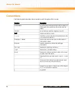
Page 12: ...aceable Unit I O Input Output IEC International Electrotechnical Commission IEEE Institute of Electrical and Electronics Engineers IMC IPMC Master Controller IPMC Intelligent Peripheral Management Controller IPMI Intelligent Platform Management Interface ISC IPMC Slave Controller ISO International Organization for Standardization LAN Local Area Network LED Light Emitting Diode MMC Mezzanine Manage...

Page 13: ...f Hazardous Substances Directive SATA Serial Advanced Technology Attachment SDRAM Synchronous Dynamic Random Access Memory SDRs Sensor Data Record SELV Safety Extra Low Voltage Circuits SERDES Serializer Deserializer SGMII Serial Gigabit Media Independent Interface SPI Serial Peripheral Interface SRAM Static Random Access Memory STP Shielded Twisted Pair ShM Shelf Manager TPE Twisted Pair Ethernet...

Page 14: ...on screenoutputandcoderelatedelements or commands in body text Courier Bold Used to characterize user input and to separate it from system output Reference Used for references and for table and figure descriptions File Exit Notation for selecting a submenu text Notation for variables and keys text Notation for software buttons to click on the screen and parameter description Repeated item for exam...

Page 15: ...ous situation which if not avoided could result in death or serious injury Indicates a hazardous situation which if not avoided may result in minor or moderate injury Indicates a property damage message No danger encountered Pay attention to important information Notation Description ...

Page 16: ...on 6806800D06B September 2007 EA version Changes made compared to previous version include updated standard requirements updated power requirements updated environmental requirements enhanced block diagram figures fabric and base interface connections as well as shelf manager cross connection figures updated IPMI sensor list added blackplane connector pinouts added section Boot and User Flashes ad...

Page 17: ...er Requirements in figure AMC Module B4 Interconnection Scheme included AdvancedTCA update channel number AND AMC port number to avoid confusion between the term port used in different contexts AMC port and ATCA update channel port updated IPMI Sensors Overview table added sections FPGA and CentralProcessingUnit updated U Boot Firmware section 6806800D06D February 2008 Added note regarding environ...

Page 18: ...ATCA F120 Installation and Use 6806800D06F About this Manual 18 About this Manual ...

Page 19: ...y Emerson or persons qualified in electronics or electrical engineering are authorized to install remove or maintain the product The information given in this manual is meant to complete the knowledge of a specialist and must not be used as replacement for qualified personnel Keep away from live circuits inside the equipment Operating personnel must not remove equipment covers Only factory authori...

Page 20: ...igh humidity and condensation on the blade surface causes short circuits Do not operate the blade outside the specified environmental limits Make sure the blade is completely dry and there is no moisture on any surface before applying power Do not operate the blade below 5 C Overheating and Blade Damage Operating the blade without forced air cooling may lead to overheating and thus damage of the b...

Page 21: ...gs before you install the blade Installation Blade Damage and Additional Devices and Modules Incorrect installation or removal of additional devices or modules may damage the blade or the additional devices or modules Before installing or removing additional devices or modules read the respective documentation Damage of Circuits Electrostatic discharge and incorrect installation and removal of the...

Page 22: ...ors could void the ECC warranty for the backplane or boards Data loss Removing the blade with the blue LED still blinking causes data loss Wait until the blue LED is permanently illuminated before removing the blade Cabling and Connectors Blade Damage The RJ 45 connector s on the face plate are twisted pair Ethernet TPE or E1 T1 J1 interfaces Connecting an E1 T1 J1 line to an Ethernet connector ma...

Page 23: ... your local Emerson sales representative if in doubt Limitation of Operating Temperature Range Installing AMC modules with small operating temperature ranges into the ATCA F120 may further restrict the operating temperature range of the ATCA F120 Make sure that the operating temperature of any installed AMC modules and the ATCA F120 as a bundle are within allowed limits Poor Shelf Cooling and EMC ...

Page 24: ...ATCA F120 Installation and Use 6806800D06F Safety Notes 24 ...

Page 25: ...lten wenden Sie sich bitte an die für Sie zuständige Geschäftsstelle von Emerson Das System erfüllt die für die Industrie geforderten Sicherheitsvorschriften und darf ausschließlich für Anwendungen in der Telekommunikationsindustrie und im Zusammenhang mit Industriesteuerungen verwendet werden Einbau Wartung und Betrieb dürfen nur von durch Emerson ausgebildetem oder im Bereich Elektronik oder Ele...

Page 26: ...führen dass der Anwender die Genehmigung zum Betrieb des Produktes verliert Boardprodukte werden in einem repräsentativen System getestet um zu zeigen dass das Board den oben aufgeführten EMV Richtlinien entspricht Eine ordnungsgemässe Installation in einem System welches die EMV Richtlinien erfüllt stellt sicher dass das Produkt gemäss den EMV Richtlinien betrieben wird Verwenden Sie nur abgeschi...

Page 27: ...auf getrennt ist und umgekehrt Prüfen Sie deshalb immer ob die Leitung spannungsfrei ist bevor Sie Ihre Arbeit fortsetzen um Schäden oder Verletzungen zu vermeiden Schaltereinstellungen Jumper Fehlfunktion des Blades Schalter die mit Reserved gekennzeichnet sind können mit produktionsrelevanten Funktionen belegt sein Das Ändern dieser Schalter kann im normalen Betrieb Störungen auslösen Verstellen...

Page 28: ...oder die Platine deformiert oder zerstört wird Beschädigung des Blades der Backplane oder von System Komponenten Verbogene Pins oder lose Komponenten können zu einer Beschädigung des Blades der Backplane oder von Systemkomponenten führen Überprüfen Sie daher das Blade sowie die Backplane vor der Installation sorgältig und stellen Sie sicher dass sich beide in einwandfreien Zustand befinden und kei...

Page 29: ...von AMC Modulen Die zwei AMC Steckplätze sind ausschliesslich vorgesehen für AMC Module welche offiziell von Emerson unterstützt werden Siehe hierzu Supported AMC Modules on page 52 Installierte AMC ModuledürfeneineVerlustleistungvon35Wnichtüberschreiten DieInstallationundder Betrieb anderer AMC Module kann sowohl die AMC Module als auch das Blade sowie ein installiertes RTM und andere angeschloss...

Page 30: ...hlung des Shelfs sowie starker elektromagnetischer Strahlung führen und somit eine Überschreitung von EMV Grenzwerten zur Folge haben Installieren Sie daher immer ein Filler Panel in einen anderweitig nicht verwendeten AMC Steckplatz Umweltschutz Entsorgen Sie alte Blades Systemkomponenten RTMs stets gemäß der in Ihrem Land gültigen Gesetzgebung wenn möglich immer umweltfreundlich ...

Page 31: ...el z One 1000Base T management interface via face plate z One Base Channel extension interface via face plate z One 1000BaseT face plate interface which connects to AMC bay B1 z Optional Rear Transition Module RTM Further features of the ATCA F120 are the following z Freescale MPC8548E PowerQUICC III CPU z At least 512 MBytes DDR2 SDRAM main memory with ECC support z Dual boot flashes of 32 MBytes...

Page 32: ...anada ICES 003 VCCI Japan AS NZS CISPR 22 EN 300 386 NEBS Standard GR 1089 CORE EMC requirements legal on system level predefined Emerson system NEBS Standard GR 63 CORE ETSI EN 300019 series Environmental requirements PICMG 3 0 Rev 2 0 AdvancedTCA Base Specification Defines mechanics blade dimensions power distribution power and data connectors and system management PICMG 3 1 Rev 1 0 AdvancedTCA ...

Page 33: ...elcordia GR 1089 R4 14 use ShieldedTwistedPair STP cables grounded at both ends to connect to the Ethernet ports The product has been designed to meet the directive on the restriction of the use of certain hazardous substances in electrical and electronic equipment RoHS Directive 2002 95 EC ...

Page 34: ...Introduction ATCA F120 Installation and Use 6806800D06F 34 Figure 1 1 Declaration of Conformity ...

Page 35: ...essories 1 4 1 Supported Blade Models As of writing this guide the following blade variants were available Consult your localEmerson sales representative for further variants that may be available Table 1 2 Mechanical Data Data Type Value Dimensions width x height x depth 30 mm x 351 mm x 312 mm Weight 2 3 Kg Table 1 3 Blade Variants Blade Variant Description ATCA F120 6E ATCA F120 equipped with 5...

Page 36: ...1 Gigabit Ethernet Fabric Channel interfaces via RJ 45 connectors z Two RJ 45 telecom clocking interface connectors for inter shelf clocking configurations The RTM is 6E RoHS compliant RTM ATCA F120 OPT The main features of this RTM are z Four 10 Gigabit Ethernet Fabric Channel uplinks via SFP connectors z Two 10 Gigabit Ethernet Base Channel uplinks via SFP connectors z Four 1 Gigabit Ethernet Ba...

Page 37: ...rAdvancedTCAsystem These main steps and their sequence are 1 Unpack and inspect the blade 2 Make sure environmental and power requirements are met 3 If applicable install Rear Transition Module RTM 4 Configure the ATCA F120 5 Install the ATCA F120 6 If applicable install AMC modules 2 2 Unpacking and Inspecting the Blade Shipment Inspection To inspect the shipment perform the following steps 1 Ver...

Page 38: ...environmental requirements specified below The blade is thoroughly inspected before shipment If any damage occurred during transportation or any items are missing please contact our customer s service immediately Operating temperatures refer to the temperature of the air circulating around the blade and not to component temperatures If you integrate the blade in your own non Emerson system please ...

Page 39: ...erating Temperature 5ºC 41 F to 40ºC 104 F normal operation according to NEBS Standard GR 63 CORE 5ºC 23 F to 55ºC 131 F exceptional operation according to NEBS Standard GR 63 CORE 40ºC 40 F to 70ºC 158 F may be further limited by installed accessories Temp Change 0 25ºC min according to NEBS Standard GR 63 CORE 0 25ºC min Rel Humidity 5 to 90 non condensing according to Emerson internal environme...

Page 40: ...Hardware Preparation and Installation ATCA F120 Installation and Use 6806800D06F 40 Figure 2 1 Critical Temperature Spots 1 2 3 4 ...

Page 41: ...orks Table 2 2 Critical Temperature Limits Location Temperature in Celsius Temperature in Fahrenheit Description 1 85 C 185 F Top center of DC DC converter used for management power 2 100 C 212 F PCB surface of main DC DC converter 3 105 C 221 F Big capacitor margin which faces the DC DC converter 4 90 C 194 F Top center of filter coil Table 2 3 DC System Power Requirements Feature Value Rated vol...

Page 42: ...ration switches SW1 SW2 SW3 and SW4 Their location is shown in the following figure The switch settings shown in the figure correspond to the default settings The switches are displayed as the small white squares The RTMs are not hot swappable Before you install them you must make sure that either no front blade is installed in the respective slot or that the front blade is powered down For furthe...

Page 43: ...Hardware Preparation and Installation ATCA F120 Installation and Use 6806800D06F 43 Figure 2 2 On Board Configuration Switches ...

Page 44: ...Base Channel port 1 or Update channel port 0 For details refer to Shelf Manager Cross Connection on page 92 Note that this switch setting can be overwritten via IPMI OFF ShM is accessed through Update Channel port 0 default ON ShM is accessed through Base Channel port 1 SW1 2 Reserved default OFF SW1 3 Reserved default OFF SW1 4 Reserved default OFF SW2 1 and SW2 2 Serial interface routing SW2 1 O...

Page 45: ...p on page 109 for further details OFF IPMI selects boot flash default ON Switch SW3 2 determines boot flash SW3 2 Determines boot flash only if switch SW3 1 is set to ON See Boot Flashes on page 83 for further details OFF Blade boots from boot flash 1 default ON Blade boots from boot flash 2 SW3 3 Watchdog timer enabling This switch allows to enable disable the watchdog inside the FPGA See Glue Lo...

Page 46: ...l the blade into an AdvancedTCA shelf proceed as follows Damage of Circuits Electrostatic discharge and incorrect blade installation and removal can damage circuits or shorten their life Before touching the blade or electronic components make sure that you are working in an ESD safe environment Damage of the blade Incorrect installation of the blade can cause damage of the blade Only use handles w...

Page 47: ...and bottom ejector handles are in the outward position by squeezing the lever and the latch together 2 Insert blade into the shelf by placing the top and bottom edges of the blade in the card guides of the shelf Ensure that the guiding module of shelf and blade are aligned properly 3 Apply equal and steady pressure to the blade to carefully slide the blade into the shelf until you feel resistance ...

Page 48: ...ed to the backplane power pins the blue LED is illuminated When the blade is completely installed the blue LED starts to blink This indicates that the blade announces its presence to the shelf management controller 6 Wait until the blue LED is switched off then tighten the face plate screws which secure the blade to the shelf If an RTM is connected to the front blade make sure that the handles of ...

Page 49: ...Blade This section describes how to remove the blade from an AdvancedTCA system Damage of Circuits Electrostatic discharge and incorrect blade installation and removal can damage circuits or shorten their life Before touching the blade or electronic components make sure that you are working in an ESD safe environment Damage of the blade Incorrect installation of the blade can cause damage of the b...

Page 50: ...tward The blue LED blinks indicating that the blade power down process is ongoing 2 Wait until the blue LED is illuminated permanently then unlatch the upper handle and rotate both handles fully outward 3 Remove face plate cables if applicable 4 Unfasten the screws of face plate until the blade is detached from shelf 5 Remove the blade from the shelf 2 7 AMC Modules The blade provides two AMC bays...

Page 51: ...Hardware Preparation and Installation ATCA F120 Installation and Use 6806800D06F 51 Figure 2 3 Location of AMC Bays AMC B1 AMC B4 ...

Page 52: ... to AMC 0 R2 0 2 7 1 1 AMC Bay B4 This AMC bay is designed to support Emerson processor AMC modules The following table describes how the AMC ports are assigned Consult your local Emerson sales representative for a list of AMC modules which Emerson has validated for the use in AMC B1 and AMC B4 Table 2 5 AMC Bay B4 Port Assignments Connector Region AMC Port Usage on ATCA F120 Clocking 1 Unused 2 U...

Page 53: ...pes of AMC modules The mechanical design allows to install single width AMCs with midsize face plates 8 Ethernet Dual MAC Intel 82671EB 9 Ethernet Dual MAC Intel 82671EB 10 Ethernet Dual MAC Intel 82671EB 11 Ethernet Dual MAC Intel 82671EB Extended Options 12 18 Unused 19 Zone 3 connector P30 row 7 pin pair A B 20 Unused Figure 2 4 AMC Module B4 Interconnection Scheme Table 2 5 AMC Bay B4 Port Ass...

Page 54: ...C Bay B1 Port Assignments Connector Region AMC Port Usage on ATCA F120 Clocking 1 CH1 CLK1 2 CH1 CLK2 3 PCI Express HCSL 100 MHz clock Common Options 0 Base Channel switch port 21 1 Fabric channel switch 2 port 17 2 AMC B4 port 2 3 AMC B4 port 3 Fat Pipes 4 AMC B4 port 4 5 AMC B4 port 5 6 AMC B4 port 6 7 AMC B4 port 7 8 Fabric Channel switch 2 port 18 9 Fabric Channel switch 2 port 19 10 Fabric Ch...

Page 55: ...ation ATCA F120 Installation and Use 6806800D06F 55 16 Differential telecom clock to and from the AMC 17 Unused 18 Unused 19 Unused 20 Unused Table 2 6 AMC Bay B1 Port Assignments continued Connector Region AMC Port Usage on ATCA F120 ...

Page 56: ...ceed a power dissipation of 35W Installing and operating other AMC modules may damage the AMC modules the blade and an installed RTM including attached devices Only install AMC modules into AMC bay B1 and B4 which are officially supported by Emerson Consult your local Emerson sales representative if in doubt Limitation of Operating Temperature Range Installing AMC modules with small operating temp...

Page 57: ...e filler panel before proceeding with the installation procedure The removal procedure for the filler panel is the same as described in the Removal procedure which follows immediately after this procedure Ignore steps that mention the blue LED 4 Ensure that the AMC module handle is in the extracted position pulled outward away from the face plate 5 Using your thumb apply equal and steady pressure ...

Page 58: ...m the ATCA F120 The procedure assumes that the ATCA F120 is powered If it is not powered the steps regarding the blue LED can be ignored and skipped 1 Make sure you are in an ESD safe environment 2 Remove any cables that are connected to the AMC module face plate connectors 3 Gently pull the module latch outwards approximately 3mm from its locked position 4 Wait for the blue LED to first perform s...

Page 59: ... basically a Linux distribution with some hardware specific add ons It consist of the following parts z A carrier grade operating system z Several custom hardware management functions for the unique hardware of the blade z A set of management routines for Linux and all hardware interfaces Management access includes support for SNMP and a local console interface based on a standard Linux command sh...

Page 60: ...ystem management functionality may be based on the widely adopted Hardware Platform Interface HPI For this purpose Emerson offers an HPI distribution which provides a set of libraries that can be used as a basis for implementing system management functionalities For details refer to the following manuals System Management Interface Based on HPI B Centellis 4000 Series and System Management Interfa...

Page 61: ...F120 Installation and Use 6806800D06F 61 Controls LEDs and Connectors 3 1 Overview This chapter describes z Mechanical layout of the blade z Face plate connectors and LEDs z Rear panel connectors z On board connectors ...

Page 62: ...Controls LEDs and Connectors ATCA F120 Installation and Use 6806800D06F 62 3 2 Blade Layout The following figure provides an overview of the mechanical layout of the blade Figure 3 1 Mechanical Layout ...

Page 63: ...Ds and Connectors ATCA F120 Installation and Use 6806800D06F 63 3 3 Face Plate Connectors and LEDs This section describes the connectors and LEDs of the blade s face plate The following figure shows the face plate ...

Page 64: ...Controls LEDs and Connectors ATCA F120 Installation and Use 6806800D06F 64 Figure 3 2 Face Plate ...

Page 65: ...nector allows to establish a serial console connection between the ATCA F120 and an external computer for example a laptop The serial interface is primarily intended for management purposes and allows for example to access the blade s U Boot firmware see Chapter 5 U Boot Firmware on page 101 The following figure shows the location of the connector This interface is typically used to connect to and...

Page 66: ...trols LEDs and Connectors ATCA F120 Installation and Use 6806800D06F 66 The connector pinout is as follows Table 3 1 Serial Connector Pinout Pin Signal 1 n c 2 RXD 3 TXD 4 n c 5 GND 6 n c 7 n c 8 n c 9 n c ...

Page 67: ...tor indicate the Ethernet connection status The LEDs are labelled A activity and L link Blade Damage The RJ 45 connector s on the face plate are twisted pair Ethernet TPE or E1 T1 J1 interfaces Connecting an E1 T1 J1 line to an Ethernet connector may damage the product z Make sure that TPE connectors near your working area are clearly marked as network connectors z Verify that the length of an ele...

Page 68: ... F120 Installation and Use 6806800D06F 68 Figure 3 4 Location of Ethernet Management Interface Table 3 2 Ethernet Management Connector Pinout Pin Signal 1000Base T 1 ETH_DA 2 ETH_DA 3 ETH_DB 4 ETH_DC 5 ETH_DC 6 ETH_DB 7 ETH_DD 8 ETH_DD ...

Page 69: ...tion status The LEDs are labelled A activity and L link Blade Damage The RJ 45 connector s on the face plate are twisted pair Ethernet TPE or E1 T1 J1 interfaces Connecting an E1 T1 J1 line to an Ethernet connector may damage the product z Make sure that TPE connectors near your working area are clearly marked as network connectors z Verify that the length of an electric cable connected to a TPE b...

Page 70: ...ws the connector location and pinout Figure 3 5 Location of AMC Module Ethernet Management Interface Connector Table 3 3 AMC Module Ethernet Interface Connector Pinout Pin Signal 1000Base T 1 ETH_DA 2 ETH_DA 3 ETH_DB 4 ETH_DC 5 ETH_DC 6 ETH_DB 7 ETH_DD 8 ETH_DD RESET 8 1 AMC Bay B1 Ethernet Interface ...

Page 71: ...Ethernet connection status The LEDs are labelled A activity and L link Blade Damage The RJ 45 connector s on the face plate are twisted pair Ethernet TPE or E1 T1 J1 interfaces Connecting an E1 T1 J1 line to an Ethernet connector may damage the product z Make sure that TPE connectors near your working area are clearly marked as network connectors z Verify that the length of an electric cable conne...

Page 72: ... 3 2 LEDs The following figure highlights the LEDs available at the face plate Figure 3 6 Location of Base Channel Extension Connector Table 3 4 Base Channel Extension Connector Pinout Pin Signal 1000Base T 1 ETH_DA 2 ETH_DA 3 ETH_DB 4 ETH_DC 5 ETH_DC 6 ETH_DB 7 ETH_DD 8 ETH_DD ...

Page 73: ...Controls LEDs and Connectors ATCA F120 Installation and Use 6806800D06F 73 Figure 3 7 Face Plate LEDs ...

Page 74: ...by the IPMC Note that this LED indicates the payload power status both in the early power state and the normal blade operation OFF Payload power is disabled ATTN Amber This LED is controlled by higher layer software such as middleware or applications H S Blue FRU State Machine During blade installation Permanently blue On board IPMC powers up Blinking blue Blade communicates with shelf manager OFF...

Page 75: ...ontrols LEDs and Connectors ATCA F120 Installation and Use 6806800D06F 75 Their location is shown in the following figure Figure 3 8 Location of AdvancedTCA Connectors P30 P31 P32 P20 P21 P22 P23 P24 P10 ...

Page 76: ...U_TX BIX_B16_U_TX IPMB1_SCL VP12_RTM n c n c n c CPU_SD_RX0_P n c n c BIX_P15_U_RX BIX_P16_U_RX IPMI_V3P3 V3P3_RTM n c n c n c CPU_SD_RX0_M n c n c BIX_P15_U_RX BIX_P16_U_RX RTM_IMC_RS_N V3P3_RTM 1 2 3 4 5 6 7 8 9 10 1 2 3 4 5 6 7 8 9 10 a b c d a b c d e f g h AMC1_P19_TX BIX_P17_TX BIX_P18_TX BIX_P19_TX BIX_P20_TX FIX2_P21_TX FIX2_P22_TX BIX_XG0_TXT RTM_PS0_N RTM_ENABLE_N AMC1_P19_RX BIX_P17_TX ...

Page 77: ..._GPO1 n c n c BIX_XG_MDIO n c n c n c n c n c n c 1 2 3 4 5 6 7 8 9 10 1 2 3 4 5 6 7 8 9 10 a b c d a b c d e f g h n c BIX_XG0_TX0 BIX_XG0_TX2 FIX2_MDIO BIX_XG1_TX0 BIX_XG0_TX3_ BIX_XG1_TX2 BIX_XG1_TX1 BIX_XG1_TX3 TXDIS_LTH_CLK n c BIX_XG0_TX0 BIX_XG0_TX2 FIX2_MDC BIX_XG1_TX0 BIX_XG0_TX3 BIX_XG1_TX2 BIX_XG1_TX1 BIX_XG1_TX3 TXDIS_SH_CLK BIX_XG1_RX1 BIX_XG1_RX0 BIX_XG0_RX2 FIX1_XG_MDC BIX_XG1_RX3 B...

Page 78: ..._RTM FIX1_P19_RX2 FIX1_P19_RX0 FIX1_P18_RX0 FIX1_P18_RX2 FIX1_P17_RX2 FIX1_P17_RX0 FIX1_P16_RX2 FIX1_P16_RX0 FIX2_P24_RX n c 1 2 3 4 5 6 7 8 9 10 1 2 3 4 5 6 7 8 9 10 a b c d a b c d e f g h FIX1_P19_TX3 FIX1_P19_TX1 FIX1_P18_TX3 FIX1_P18_TX1 FIX1_17_TX3 FIX1_P17_TX1 FIX1_P16_TX3 FIX1_P16_TX1 FIX2_P23_TX RTM_PS0_N FIX1_P19_TX3 FIX1_P19_TX1 FIX1_P18_TX3 FIX1_P18_TX1 FIX1_P17_TX3 FIX1_P17_TX1 FIX1_P...

Page 79: ...rview In this chapter you will find the following information z Block diagram z Central Processing Unit z Main memory z Glue Logic FPGA z Boot and user flashes z Fabric channel interfaces z Base channel interfaces z Base interface extension z Intelligent Peripheral Management Controller ...

Page 80: ...late 1G to partner s BIX 1G to partner s PrAMC 4x 1G AMC Bay B4 PowerQUICC CPU MPC8548E RAM Flash 1G IPMC ShMC 10 100 to partner s BBP 1G Mgmt PCI AMC Bay B1 x4 PCIe 2x SAS SATA Dual Block Transfer 15 x 1 10G 15 x 1G 1G to partner s PrAMC Base Interface IPMBs RTM 4 x 10G Base Interface Switch BCM56502 24 x 1G 2 x 10G 1G 10 100 to SAM 5 x 1G Dual MAC 1G x4 PCIe RS232 1G Base Interface Switch Extend...

Page 81: ...hernet MACs z Two I2C controller z Security engine z XOR engine z JTAG interface z Watchdog not used on ATCA F120 4 4 Main Memory The memory controller resides inside the MPC8548E PowerQUICC III CPU The memory bus is 64 bit wide and ECC protected It connects the CPU to the on board memory modules The memory data bus runs at a maximum frequency of 266 MHz providing a total bandwidth of 4 267 GBytes...

Page 82: ...tion the FPGA loads its bit stream from one outoftwo serial PROMs connected to the FPGA One serial PROM acts as stand by the other as active device During blade production both serial PROMs are programmed with identical images You can switch between active and stand by serial PROM via an IPMI command For details refer to the ATCA F120 Control via IPMI Programmer s Reference Section System Boot Opt...

Page 83: ...h are Intel Strata flash devices which are programmed with identical images during the blade production Each flash device has a size of 32 MBytes The boot flashes contain the U Boot firmware as well as the Linux kernel images For details refer to Memory Map on page 109 By default the ATCA F120 always boots from boot flash 1 The boot flash device from which tobootafter the nextreset powercyclecan b...

Page 84: ...GbE 1GbEthernet ports Twenty four 1Gb Ethernet ports two 10GbEthernet ports Architecture StrataXGS StrataXGS Switching capacity 200 Gbps at line rate 196 Gbps at line rate Service classes Support for eight classes of service CoS per port Support for eight classes of Service CoS plustwoadditionalclassesfor Flow Control and system management per port Scheduling mechanism Support for deficit round ro...

Page 85: ...licing priority tagging and remapping z Extended security and ACL filtering Support for z Line rate multifield packet classification z Supports IEEE 802 1p TOS DiffServ rate limiting policing priority tagging and remapping z Extended security and ACL filtering IPv6 Support Fully supported Fully supported Table 4 1 Main Features of Fabric Channel Interface Switches continued Feature Broadcom BCM568...

Page 86: ...are interconnected A detailed description of the port assignment is given afterward Figure 4 2 On Board Routing of Fabric Interfaces Backplane RTM FIX 1 BCM56800 FIX 2 BCM56502 4 x 1000Base BX 4 x 10GBase BX4 15 x 10GBase BX4 1 x HiGig CPU MPC8548 PCI 32 66 SERDES QuadPHY BCM5466 QuadPHY BCM5466 4xRGMII ETH 82571EB ETH 82571EB AMC B1 AMC B4 PCIExpress 5xSERDES 1xSERDES Fabric Channel ...

Page 87: ...ric Channel 2 10GBase BX4 xe2 SERDES Fabric Channel 3 10GBase BX4 xe3 SERDES Fabric Channel 4 10GBase BX4 xe4 SERDES Fabric Channel 5 10GBase BX4 xe5 SERDES Fabric Channel 6 10GBase BX4 xe6 SERDES Fabric Channel 7 10GBase BX4 xe7 SERDES Fabric Channel 8 10GBase BX4 xe8 SERDES Fabric Channel 9 10GBase BX4 xe9 SERDES Fabric Channel 10 10GBase BX4 xe10 SERDES Fabric Channel 11 10GBase BX4 xe11 SERDES...

Page 88: ...00Base BX ge1 SERDES Dual MAC device 1000Base BX ge2 unused ge3 unused ge4 unused ge5 unused ge6 unused ge7 unused ge8 unused ge9 unused ge10 unused ge11 unused ge12 unused ge13 unused ge14 unused ge15 SERDES AMC Bay B1 Port 11 1000Base BX ge16 SERDES AMC Bay B1 Port 1 1000Base BX ge17 SERDES AMC Bay B 1 Port 8 1000Base BX ge18 SERDES AMC Bay B 1 Port 9 1000Base BX ge19 SERDES AMC Bay B 1 Port 10 ...

Page 89: ...itch device for Base Channel interfaces Since this is the same device that is used for one of the fabric switch devices you can find the features here Table Main Features of Fabric Channel Interface Switches on page 84 ge23 SERDES RTM 1000Base BX Table 4 3 FIX 2 Ethernet Port Assignment continued Physical Port PHY SERDES Destination Interface Type ...

Page 90: ...e 4 3 On Board Routing of Base Interfaces Backplane Backplane BIX BMC56502 BIX Extender CPU MPC8548E PCI 32 66 QuadPHY BCM5466 1000Base T RTM 4xRGMII SERDES 4x1000 BX 2x10G AMC B4 AMC B1 ETH 82571EB SERDES SERDES PCIExpress XFMR XFMR XFMR XFMR XFMR XFMR MAX 4891 MAX 4891 2x100B TX 100B TX Upd Channel 1000B BX Upd Channel QuadPHY BCM5466 XFMR XFMR 16xSGMII 1000B T XFMR XFMR 15x 1000B T ...

Page 91: ...0Base T ge2 PHY Base Channel 3 1000Base T ge3 PHY Base Channel 4 1000Base T ge4 PHY Base Channel 5 1000Base T ge5 PHY Base Channel 6 1000Base T ge6 PHY Base Channel 7 1000Base T ge7 PHY Base Channel 8 1000Base T ge8 PHY Base Channel 9 1000Base T ge9 PHY Base Channel 10 1000Base T ge10 PHY Base Channel 11 1000Base T ge11 PHY Base Channel 12 1000Base T ge12 PHY Base Channel 13 1000Base T ge13 PHY Ba...

Page 92: ...iguration switch and via an OEM IPMI command where the OEM IPMI command overrides the on board switch ifboth settingsare different Referto section Configuring theBladeon page 42 and the ATCA F120 Control via IPMI Programmer s Reference for further details ge23 SERDES Base interface update channel 1000Base T xe0 SERDES RTM XAUI xe1 SERDES RTM XAUI Table 4 4 Base Channel Switch Port Assignment conti...

Page 93: ...e illustrates this interconnection option Alternatively port 0 and 1 of Base Channel Interface 1 are used to connect to the two shelf managers in a system This type of shelf manager interconnection is compliant to the PICMG 3 0 R2 0 ECN 3 0 2 0 001 standard and is used in Centellis 4100 systems Figure 4 4 Shelf Manager Cross Connection via Update Channel Shelf Manager 1 Shelf Manager 2 ETH 1 A5 D5...

Page 94: ...he remaining two micro controllers both are Atmega168L devices serve as IPMC Slave Controllers ISC and provide an on board memory flash memory of 168 kBytes each Both are referred to as ISC0 and ISC1 An installed RTM furthermore provides an Mezzanine Management Controller MMC which is connected to the IPMC through an IPMB L bus The MMC contains an Atmega 128L micro controller For details about the...

Page 95: ...dog One of the main tasks of the IPMC is to control the power up and power down of the blade For this purpose the IPMC is connected to the on board power supply module via control and status lines Various on board IPMI sensors provide detailed information on the current power status of the blade to any interested party connected to the IPMI network The following figure gives an overview of the IPM...

Page 96: ... The 64 byte FIFO of the BT interface resides in the Glue Logic FPGA The first channel is used for standard operation between CPU and IPMC The second channel is used for system critical events to bypass the first channel For details about supported IPMI commands as well as Sensor Data Records SDRs and Field Replaceable Unit FRU information provided by the IPMC refer to the ATCA F120 Control via IP...

Page 97: ...which are accessible via IPMI Some of these sensors measureon boardtemperatures Theirnamesandlocationsareshowninthefollowingfigure Figure 4 7 Location of IPMI Temperature Sensors CPUTemp Top Edge Temp BIXTemp underneath heat sink Comp Side2 Temp Bottom Edge Temp FIX1Temp undeneath heat sink FIX2Temp underneath heat sink ...

Page 98: ...While payload powered 1 25V BIX Voltage While payload powered 1 25V FIX2 Voltage While payload powered 1 2V Base Voltage While payload powered 1 8V Base Voltage While payload powered 1 8V CPU Voltage While payload powered 12V Primary Voltage While payload powered 2 5V Voltage While payload powered 3 3V MAC Voltage Always 3 3V Mgmt AMC B1 Voltage Always 3 3V Mgmt AMC B4 Voltage Always 3 3V Mgmt RTM...

Page 99: ...vision While payload powered F120 FPGA Vers Emerson Firmware Revision Always F120 HotSwap PICMG 3 0 FRU HotSwap Always F120 IPMB0 State PICMG 3 0 IPMB Physical Link Always F120 IPMC Emerson IPMC Status Always F120 Watchdog Watchdog 2 Always FIX1 Temp Temperature Always FIX2 Temp Temperature Always HotSwap AMC B1 PICMG 3 0 FRU HotSwap Always HotSwap AMC B4 PICMG 3 0 FRU HotSwap Always HotSwap F120 ...

Page 100: ...implemented in the IPMC firmware It is configured via IPMI commands and controls the operation of the blade s payload Your software may enable disable and configure the watchdog at any time using IPMI commands For details refer to the IPMI V 1 5 specification By default the watchdog is disabled ...

Page 101: ... general information about U Boot refer to the following website http www denx de wiki UBoot WebHome 5 2 Accessing U Boot via the Serial Console Procedure You can access U boot via the serial interface connector at the face plate of the ATCA F120 For this purpose you need a computer such as a laptop with a terminal emulation software such as HyperTerm running on it Furthermore this computer must h...

Page 102: ...ce and enter into a command line interface mode If you want to disable the auto boot feature of U boot and thus make sure that U boots directly enters into the command line interface mode after the next reboot power up enter the following command setenv bootdelay 1 saveenv 5 3 Selecting Boot Options This section describes how to configure U boot for different boot options These serial access param...

Page 103: ...y the IP address of theATCA F120itself andof theTFTP serverwhich contains the Linux kernel image by entering the following U Boot commands setenv ipaddr IP address of ATCA F120 setenv serverip IP address of TFTP server 3 Specify the names of the Linux kernel image and of the NFS root directory setenv bootfile Linux kernel image file name setenv rootpath NFS root directory 4 Configure U boot to use...

Page 104: ... that the U Boot command ramboot has previously been defined Refer to the U Boot documentation for details 1 Connect to U boot as described in Accessing U Boot via the Serial Console on page 101 2 SpecifytheIPaddressoftheATCA F120itselfandoftheTFTPserverwhichcontains the RAM disk image file by entering the following U Boot commands setenv ipaddr IP address of ATCA F120 setenv serverip IP address o...

Page 105: ...ntain two redundant root file systems The user flashes are NAND flash devices See also Table Linux Devices on page 110 for details This section describes how to configure U boot to boot a Linux kernel stored in the boot flash and to mount the root file system in the user flash The procedure uses the U Boot script flashboot which has been predefined by Emerson Procedure In order to configure U boot...

Page 106: ...stem Boot Options feature Refer to the ATCA F120 Control via IPMI Programmer s Reference for details Alternatively you can use the U Boot command bootsel Its usage is bootsel 0 1 switch where 0 selects boot flash 0 1 selects boot flash 1 and switch selects the currently stand by boot flash Generally there is a fixed link between the U Boot firmware and the kernel image in the respective boot flash...

Page 107: ... particular memory region for the persistent storage of application specific data Analyzing Kernel Log Files after a Kernel Panic If the Linux OS running on your ATCA F120 indicates a kernel panic and you wish to analyze the cause of it then you can issue a reset via the face plate button for example and subsequently analyze kernel log files Because of the persistent memory feature these log files...

Page 108: ...f a persistent memory region which you can use for the storage of application specific data In order to define such a memory region you may want to use the standard U Boot variable pram It allows to reserve a memory region at the end of the physical memory which is not overwritten by U Boot Furthermore U Boot will report less memory to the Linux kernel via the mem parameter so that Linux will not ...

Page 109: ... KBytes User NAND flash 1 bank 1 control registers 0xF4000000 64 KBytes User NAND flash 1 bank 2 control register 0xF4100000 64 KBytes User NAND flash 2 bank 1 control registers 0xF5000000 64 KBytes User NAND flash 2 bank 2 control registers 0xF5100000 64 KBytes Stand by boot flash 0xFC000000 32 MBytes Active boot flash 0xFE000000 32 MBytes Regardless which of the two boot flashes is selected as t...

Page 110: ...F Active boot flash dev mtd3 U boot image 0xFFF80000 0xFFFFFFFF Active boot flash dev mtd4 combined 0xFE000000 0xFFFFFFFF Active boot flash dev mtd5 U Boot boot parameters 0xFC000000 0xFC01FFFF Stand by boot flash dev mtd6 Kernel image 0xFC020000 0xFC51FFFF Stand by boot flash dev mtd7 Empty 0xFC052000 0xFD7FFFFF Stand by boot flash dev mtd8 U Boot image 0xFDF80000 0xFDFFFFFF Stand by boot flash d...

Page 111: ...OST Result Format Offset Description 0x0 Magic word 0xAA55FCE0 0x04 CRC32 checksum over the POST result string 0x08 POST result string This is a zero terminated string which is based on the following XML like syntax T tag E Error_description E T tag identifies the device that was tested If no POST error was detected then the closing tag T follows immediately after the opening tag Error_Description...

Page 112: ...e CRC mismatch detected 0x0D Wrong CPU speed 0xfd Emerson specific POSTerrorcode Furtherinformation is provided in the event data byte 3 see Table SYS FW PROGRESS IPMI Sensor POST Error Event Codes on page 112 0x00 One of the remaining POST errors was detected Table 5 5 SYS FW PROGRESS IPMI Sensor POST Error Event Codes Event Data Byte 3 Description 0x1E Error accessing the switch devices 0x03 Err...

Page 113: ...y mapped register Base interface extender SPI Data test on LED register page 0 offset 0x12 I2C buses Check whether bus addresses 0x31 0x44 0x46 0x47 0x50 0x51 are accessible on bus 0 and 0x50 0x70 on bus 1 RTC Checks whether the second counter is advancing Compares the number of CPU ticks in one second against the expected system clock frequency 66 MHz MDIO PHY Attempts to read model and device ID...

Page 114: ...enable 5 9 ATCA F120 Specific U Boot Commands The following table lists ATCA F120 specific U boot commands Table 5 7 Environment Variable post_control Value Description never Disables POST altogether always POST is executed after all types of blade resets hard POST is executed only after hard resets A hard reset is a reset of the entire payload and can be issued by the following reset sources z Wa...

Page 115: ...al loopback mode firmware_build Firmware build count read only inicmd Can beusedto defineacommand sequenceto beexecutedat the end of the boot sequence i e before the shell or bootcmd are executed noboot When set to 1 the boot sequence is stopped before control is transferred to the Linux operating system and the boot parameters are printed on the screen drvargs Contains blade specific values for t...

Page 116: ...dog reset z ini_wdog Initial watchdog reset post_result Contains the POST result string if POST has been executed post_result_adrs Address where the POST result string is copied to immediately before executing the operating system mtdroot When using the flashboot boot parameter this specifies what mtd device is to be used as root device default is dev mtdblock rom_corruption Set to 1 if the CRC of...

Page 117: ... following U Boot commands setenv ipaddr IP address of ATCA F120 setenv serverip IP address of TFTP server 3 Depending on your network configuration you may have to specify a gateway IP address as well as a netmask To do so use the following commands setenv gatewyip gateway IP setenv netmask netmask 4 Load the image to the RAM We recommend to update the U boot firmware via BBS Linux or via the she...

Page 118: ...fdffffff done Erased 7 sectors protect off 2 252 258 addresses to the currently stand by U Boot bank while protect off 1 252 258 addresses the currently active U Boot bank The currently stand by U boot bank is always mapped to the start address 0xFD000000 while the currently active U boot bank is always mapped to 0xFE000000 If you wish to set a particular U boot bank into the active state then you...

Page 119: ...19 7 Copy the image from the RAM to the currently stand by U boot bank cp b loadaddr fdf80000 80000 Copy to Flash done 8 Make stand by U boot active and vice versa by entering the following command bootsel switch 9 In order to boot the new U Boot reset the blade ...

Page 120: ...U Boot Firmware ATCA F120 Installation and Use 6806800D06F 120 ...

Page 121: ...eck the Emerson website or consult your local Emerson sales representative for release notes or errata sheets that may be applicable to the ATCA F120 RTM ATCA F120C or RTM ATCA F120 OPT Table A 1 Emerson Publications Document Title and Source Publication Number RTM ATCA F120 Installation and Use 6806800D07 ATCA F120 Control via IPMI Programmer s Reference 6806800D18 RTM ATCA F120 Control via IPMI ...

Page 122: ...o change without notice Table A 2 Related Specifications Organization Document Title Intel developer intel com design servers ipmi Platform Management FRU Information Storage Definition v1 0 IPMI Specification v1 5 PICMG picmg org specifications stm PICMG 3 0 Revision 2 0 Advanced TCA Base Specification PICMG 3 1 Revision 1 0 Specification Ethernet Fiber Channel PICMG AMC 0 R2 0 Advanced Mezzanine...

Page 123: ...allation procedure 46 Power requirements 41 Removal procedure 49 Installation procedure 46 IPMC 94 IPMI 94 ISC0 1 96 On board IPMI structure 95 On board sensors 97 Watchdogs 99 L LEDs 72 M Main features 31 Mechanical data 35 Memory maps 109 N NAND flashes 83 O On board switches 42 Operating voltages 41 P Power on self test 111 R Rear transition modules 42 Removal 49 S Serial interface 65 Shelf man...

Page 124: ...Index ATCA F120 Installation and Use 6806800D06F 124 ...

Page 125: ......

Page 126: ...Network Power logo are trademarks and service marks of Emerson Electric Co All other product or service names are the property of their respective owners 2009 Emerson Electric Co Emerson Network Power The global leader in enabling Business Critical Continuity AC Power Systems Connectivity DC Power Systems Embedded Computing Embedded Power Integrated Cabinet Solutions Outside Plant Power Switching ...

Reviews: