Controls, LEDs and Connectors
ATCA-F120 Installation and Use (6806800D06F
)
76
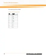
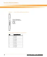
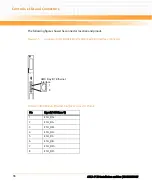
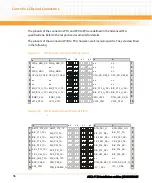
The pinouts of the connectors P10 and P20 to P24 are defined in the AdvancedTCA
specifications. Refer to the respective documents for details.
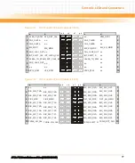
The pinouts of the connectors P30 to P32, however, are Emerson-specific. They are described
in the following.
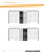
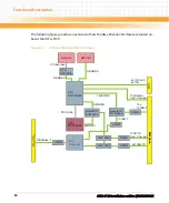
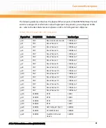
Figure 3-9
P30 Connector Pinout (Columns A to D)
Figure 3-10 P30 Connector Pinout (Columns E to H)
FPGA_SER_TX
n.c.
FPGA_MDIO
CPU_SD_TX0_M
n.c.
n.c.
BIX_P15_U_TX-
BIX_P16_U_TX-
IPMB1_SDA
VP12_RTM
FPGA_SER_RX
n.c.
FPGA_MDC
CPU_SD_TX0_P
n.c.
n.c.
BIX_P
BIX_B
IPMB1_SCL
VP12_RTM
n.c.
n.c.
n.c.
CPU_SD_RX0_P
n.c.
n.c.
BIX_P
BIX_P
IPMI_V3P3
V3P3_RTM
n.c.
n.c.
n.c.
CPU_SD_RX0_M
n.c.
n.c.
BIX_P15_U_RX-
BIX_P16_U_RX-
RTM_IMC_RS_N
V3P3_RTM
1
2
3
4
5
6
7
8
9
10
1
2
3
4
5
6
7
8
9
10
a
b
c
d
a b
c d
e f
g h
AMC1_P19_TX
BIX_P17_TX-
BIX_P18_TX-
BIX_P19_TX-
BIX_P20_TX-
FIX2_P21_TX-
FIX2_P22_TX-
BIX_XG0_TXT-
RTM_PS0_N
RTM_ENABLE_N
AMC1_P19_RX
BIX
BIX
BIX
BIX
FIX2
FIX2
BIX_
BRD_PS0_N
VP5_RTM
RTM_PS1_N
BIX
FIX2
FIX2
BIX
BIX
BIX
n.c.
RTM_RS_KEY_N
I2C_1_SCL
RTM_PWR_GD
BIX_P17_TX-
FIX2_P21_RX-
FIX2_P22_RX-
BIX_P18_RX-
BIX_P19_RX-
BIX_P20_RX-
n.c.
RTM_RS_OUT_N
I2C_1_SDA
1
2
3
4
5
6
7
8
9
10
1
2
3
4
5
6
7
8
9
10
e
f
g
h
a b
c d
e f
g h
_
Summary of Contents for ATCA-F120
Page 6: ...ATCA F120 Installation and Use 6806800D06F Contents 6 Contents Contents ...
Page 8: ...ATCA F120 Installation and Use 6806800D06F 8 List of Tables ...
Page 10: ...ATCA F120 Installation and Use 6806800D06F 10 List of Figures ...
Page 18: ...ATCA F120 Installation and Use 6806800D06F About this Manual 18 About this Manual ...
Page 24: ...ATCA F120 Installation and Use 6806800D06F Safety Notes 24 ...
Page 120: ...U Boot Firmware ATCA F120 Installation and Use 6806800D06F 120 ...
Page 124: ...Index ATCA F120 Installation and Use 6806800D06F 124 ...
Page 125: ......

